








Introduction
Pressure piping operating above ambient temperature must be designed using reduced allowable stresses. Otherwise, the calculation of the Maximum Allowable Working Pressure (MAWP) may give rise to safety hazards. When pipes operate at high temperatures, the strength of the material undergoes predictable degradation. To determine the safe operating range, engineers must take into account both the physical and geometric parameters of the pipe and the temperature-dependent material properties. The European standard EN 10217-2 specifies the technical delivery conditions for welded steel pipes made of non-alloy and alloy steels with specific high-temperature properties, and forms an important basis for the design of pressure equipment within the framework of the EU Pressure Equipment Directive (PED) 2014/68/EU.
This guide explains how engineers can calculate the maximum allowable working pressure (MAWP) of EN 10217-2 P235GH and P265GH pipes using wall thickness and temperature-dependent design stresses. Emphasis is placed on how wall thickness selections, drawn from reliable dimensional tables, interact with temperature derating factors. The aim is to deliver a transparent, code-compliant calculation path without overstating material capabilities, while keeping the discussion objective and technically accurate.
Decoding EN 10217-2: Welded Steel Pipes for Pressure Purposes
EN 10217-2 specifically covers electric welded non-alloy and alloy steel pipes intended for pressure applications at room and elevated temperatures. The standard defines mandatory tests, dimensional tolerances, and technical requirements for welded steel pipe products used in critical service. Within this framework, grades P235GH and P265GH are widely specified.
The designation “P” indicates suitability for pressure purposes. The numeric part—235 or 265—represents the minimum yield strength in megapascals at ambient temperature. The suffix “GH” denotes confirmed elevated temperature properties: the steel has been tested and validated for creep and high-temperature yield. Chemically, P235GH typically limits carbon to 0.16% and manganese to 1.20%, while P265GH allows slightly higher carbon (up to 0.20%) and manganese (up to 1.40%) to achieve its enhanced strength. Both grades offer fine-grain structure and excellent weldability, but their strength advantage diminishes as temperature rises, making temperature derating an indispensable part of pressure calculation. Reliable calculations begin with pipes that meet the specified dimensional tolerances and mechanical property requirements.
The Barlow’s Formula Adaptation for EN 10217-2 P265GH Grade Steel
The classic Barlow’s formula for thin-walled cylinders, P = (2 · S · t) / D, serves as the basis, where S is allowable stress, t is wall thickness, and D is outside diameter. However, engineering codes such as EN 13480-3 (Metallic industrial piping) and ASME B31.3 refine this equation to account for weld integrity and design safety factors.
For a straight pipe with a longitudinal weld under internal pressure, the code-adapted formula for MAWP is generally expressed as: MAWP = [2 · f · z · (t – c₁ – c₀)] / [Dₒ – (t – c₁ – c₀)]
Where:
- f = design stress (derived from yield or tensile strength divided by safety factor, and temperature derated)
- z = joint efficiency factor (e.g., 1.0 for fully radiographed LSAW, 0.85 for typical ERW)
- t = nominal wall thickness
- c₁ = wall thickness tolerance (negative tolerance per EN 10217-2, e.g., -10% or as agreed)
- c₀ = corrosion allowance
- Dₒ = outside diameter
When pipe dimensions and weld quality are verified through certified inspection records, engineers can apply the joint efficiency factor with greater confidence. The calculations that follow assume standard EN tolerances and a corrosion allowance of 0.5 mm, showing how even small deviations in manufacturing can shift the MAWP by several bar.
Step-by-Step Calculation: Determining MAWP for DN80 Pipes
To illustrate the interaction of wall thickness and temperature derating, we will calculate the MAWP for a DN80 (88.9 mm OD) P265GH pipe at various design temperatures.
Step 1: Determine Pipe Geometry Using a Pipe Wall Thickness Chart
A standard pipe wall thickness chart for EN-series pipes provides the dimensional references. For DN80, common wall thicknesses are 3.2 mm, 4.0 mm, and 5.6 mm. Selecting a nominal wall thickness of 5.6 mm, and after subtracting the typical EN 10217-2 negative tolerance of 10% (-0.56 mm) and a corrosion allowance of 0.5 mm, the effective thickness teff = 5.6 – 0.56 – 0.5 = 4.54 mm. Relying on accurate dimensional tables ensures the geometric input data for the pressure calculation is both standardized and traceable.
Step 2: Determine Temperature Derating Factor (Design Stress)
EN 13480-3 provides the nominal design stress f for P265GH as a function of temperature. At 20°C, the design stress equals 177 MPa. As temperature increases, f decreases to reflect loss of strength and onset of creep. The table below summarizes typical values.
| Temperature (°C) | Design Stress f (MPa) for P265GH |
| 20 | 177 |
| 100 | 168 |
| 200 | 150 |
| 250 | 135 |
| 300 | 114 |
| 350 | 97 |
| 400 | 76 |
Table 1: Temperature-dependent design stress for P265GH. (Data sourced from EN 13480-3:2017 and EN 10217-2:2019, published by the European Committee for Standardization.)
Step 3: MAWP Calculation Example at 250°C
Assume a fully radiographed LSAW pipe with joint factor z=1.0. Using the effective thickness and design stress at 250°C: MAWP = (2 · 135 · 1.0 · 4.54) / (88.9 – 4.54) = 1225.8 / 84.36 ≈ 14.53 MPa (approx. 145.3 bar)
If we now consider the same DN80 pipe but with a thinner wall of 3.2 mm (effective thickness after tolerance and corrosion 1.94 mm), the MAWP at 250°C drops to roughly 6.2 MPa. The comparison shows why both wall thickness and temperature derating must be considered in every MAWP calculation. Piping systems designed for ambient conditions cannot be safely operated at high temperatures without recalculating the MAWP using the appropriate temperature-adjusted stress.
How Hardness Data Correlate with High-Temperature Pressure Retention
A carbon steel hardness chart correlates Brinell (HB) or Vickers (HV) hardness values with ultimate tensile strength. For typical non-alloy carbon steels like P235GH and P265GH, an approximate conversion is: Tensile Strength (MPa) ≈ 3.2 × HB. Although hardness conversion provides only an estimate, it is widely used as a practical screening method during field inspections.
When a pressure pipe operates at elevated temperatures for years, microstructural degradation such as spheroidization of pearlite, decarburization, or creep cavitation can occur. These aging effects manifest as a measurable reduction in hardness. A field hardness test compared to the baseline hardness reference data can indicate whether the material has lost significant strength. For instance, if the original HB was 140 (roughly 450 MPa tensile) and in-service readings drop below 110 HB in the heat-affected zone of a welded joint, the design stress f used in the original MAWP calculation may no longer be valid. A hardness anomaly may signal a reduction in creep resistance, which directly impacts the pressure retention capability of the piping system. Maintenance engineers often use hardness changes as an early indication of material degradation before performing more detailed inspections. Pressure integrity should therefore be evaluated throughout the service life of the piping system rather than only during the initial design stage.
Conclusion
Accurate MAWP calculations depend on combining verified pipe dimensions with temperature-adjusted allowable stresses. Ignoring the negative thickness tolerance, corrosion allowance, or the drop in design stress at elevated temperatures can lead to overestimation of safe operating pressure. Practical tools such as dimensional tables and hardness reference data are indispensable for both design and in-service evaluation.
For procurement professionals, the integrity of these calculations relies entirely on the pipe meeting its specified dimensions and material properties. A competent carbon steel pipe manufacturer also provides the documentation and testing records needed to demonstrate PED compliance, supporting engineering projects without compromising on safety or delivery.
Frequently Asked Questions
Q1: What is the difference between P235GH and P265GH in EN 10217-2?
Both are non-alloy steels with guaranteed elevated temperature properties. P265GH has a higher minimum yield strength (265 MPa vs. 235 MPa) at room temperature, allowing for higher design stresses at moderate temperatures. However, above 400°C the strength difference narrows significantly; material selection should be based on the specific temperature and pressure envelope.
Q2: Why is joint efficiency critical for pressure-rated welded pipe?
The longitudinal weld is often the most sensitive region of a welded steel pipe. The joint efficiency factor accounts for potential weld imperfections. Pipes with full volumetric NDT can achieve a factor of 1.0, whereas non-tested welds must use a reduced factor, significantly lowering the MAWP. Trustworthy inspection data are therefore essential for pressure integrity.
Q3: How often should I verify the hardness of in-service carbon steel pressure pipes?
Periodic hardness monitoring is recommended as part of a risk-based inspection program, especially for pipes operating in the creep range (above approximately 370°C for P235GH/P265GH). If the hardness drops more than 10–15% from the baseline, a fitness-for-service assessment is advisable.
Q4: What role does a hardness conversion chart play in assessing pressure pipe integrity?
A carbon steel hardness chart allows engineers to convert field hardness readings into approximate tensile strength values. Comparing these with the original material certification helps identify strength loss due to high-temperature aging. A reliable hardness conversion table thus acts as a practical screening tool, indicating whether the pipe still meets its design stress assumptions or if a de-rating is necessary.

ASTM A53 vs. API 5L: A Guide to Selection and Application
In the field of industrial piping, ASTM A53 and API 5L are two key standards that are widely used, but have very different positions. ASTM...

Introduction:Technology differences determine success or failure, and selection needs to be “precise”
In oil and gas transmission, municipal infrastructure and other major projects, the reasonable choice of steel pipe welding process directly affects the project...
Steel Density Analysis: Core Differences between Mild and Medium Carbon Steels and Industrial Applications
The density of steel is one of the key parameters that determine its physical properties and industrial applications. Theoretical state of steel density...
3LPE coated steel pipe: a solid barrier in the field of industrial corrosion protection
In the harsh environment of oil and gas, chemical industry, urban pipe network, etc., the long-term reliability and corrosion resistance of pipeline system...
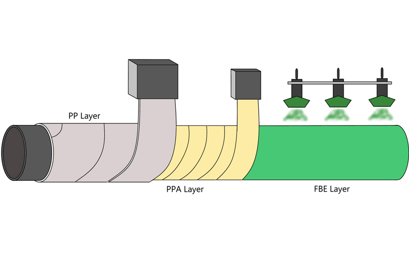
3LPP coated pipe: anti-corrosion guard in high temperature and high pressure environment
In some challenging special environments such as deep-sea oil and gas exploration and high-temperature crude oil transportation, traditional anti-corrosion coatings face significant challenges,...
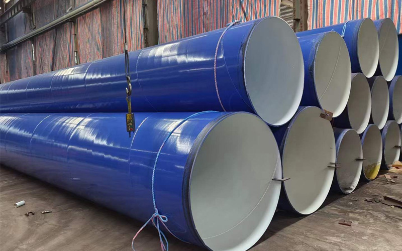
FBE steel pipe: the technological armor of the steel defense line
I In the icy waters beneath the Norwegian Sea pipeline, a section of FBE Lined Carbon Steel Pipe has been in service for 25...