


1. Introduction: The Critical Challenge of Field Pipeline Construction
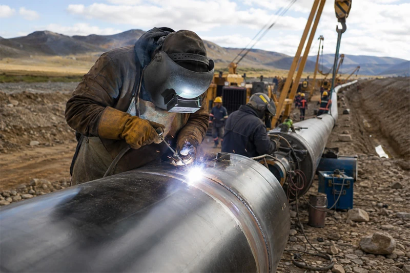
Long-distance pipeline projects—whether for oil, natural gas, or water transmission—present challenges that are fundamentally different from those in a controlled mill environment. In a controlled factory setting, production benefits from stable temperatures, calibrated machinery, and consistent material handling. In the field, crews must contend with changing weather, uneven terrain, logistical bottlenecks, and the sheer difficulty of aligning massive pipe sections that weigh several tonnes each.
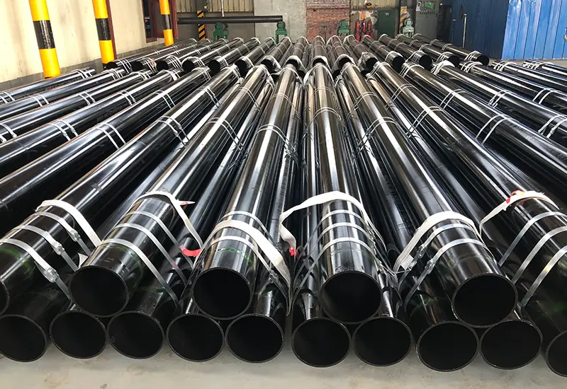
The LSAW steel pipe (Longitudinal Submerged Arc Welded pipe) is the preferred choice for many long-distance transmission projects due to its superior dimensional accuracy, straightness, and weld uniformity. Large-diameter variants—typically ranging from 406mm to 1524mm in outer diameter with wall thicknesses up to 60mm—are commonly specified for high-pressure oil and gas trunk lines. Yet these very attributes that make these large-diameter pipes desirable—large diameter and heavy wall thickness—also amplify the difficulties of field fit-up and welding.
The purpose of this article is to serve as a practical reference for field welding engineers on misalignment control, preheating specifications for high-grade steels, crack prevention strategies, and field NDT acceptance criteria. The guidance draws upon API 1104, ASME B31.8, and API 5L standards, with the goal of helping practitioners achieve consistent joint integrity across thousands of field girth welds.
2. Managing Fit-Up and Misalignment in Heavy-Walled LSAW Joints
Field fit-up is arguably the most critical variable affecting girth weld quality. Large-diameter LSAW steel pipe sections are susceptible to minor out-of-roundness during transport, handling, and lifting operations. Even a small deviation in roundness can translate into significant misalignment—commonly referred to as “high-low” or internal offset—when two pipe ends are brought together for welding.
The consequences of excessive misalignment are well documented. High-low conditions create local stress concentrations at the weld root, which can serve as initiation sites for fatigue cracking during the pipeline’s operational life. In severe cases, misalignment can also impede complete root penetration, leaving unfused areas that compromise joint integrity.
Allowable Misalignment Limits
API 1104, the primary welding standard for cross-country pipelines, focuses more on weld integrity than strict fit-up dimensions. The preferred root gap is 1.6mm (1/16 inch), with a maximum root gap of 3.2mm (1/8 inch). For high-low misalignment, API 1104 does not prescribe a fixed numerical limit, but leaves acceptance criteria to project specifications or engineering judgment.
ASME B31.8, which governs gas transmission and distribution piping, provides more specific guidance. For piping systems operating at hoop stress of 20% or more of the specified minimum yield strength, the internal offset between adjoining ends should not exceed 2.4mm (3/32 inch) without special treatment. Where the offset exceeds this limit and inside access for welding is available, a taper not exceeding 3:1 (approximately 18.4°) is required.
As a general rule of thumb, many project specifications limit radial misalignment to 10% of the wall thickness of the thinner member, with an absolute maximum of 1.6mm (1/16 inch) for critical applications.
Field Fit-Up Best Practices
To achieve these tolerances consistently, field crews should prioritize the following practices:
- Use internal line-up clamps (ILUC) for large-diameter LSAW steel pipe. Internal clamps provide superior roundness control and distribute clamping forces evenly around the pipe circumference, minimizing localized stress.
- When wall thickness variations exist between adjoining pipes, consider counter-boring the thicker pipe end or grinding a tapered transition to achieve smooth internal alignment.
- Verify fit-up with feeler gauges and bridge gauges before proceeding with tack welding. Root gap and high-low should be checked at multiple circumferential positions.
- Where dimensional deviations are unavoidable, consult the Welding Procedure Specification (WPS) for approved remedial measures, which may include build-up welding followed by re-machining or grinding.
3. Preheating and Interpass Temperature Specifications for High-Grade Steels (API 5L X65/X70)
High-strength pipeline steels such as API 5L X65 and X70 are increasingly specified for long-distance transmission projects due to their favorable strength-to-weight ratios. The numerical designation—X65 and X70—refers to the yield strength of pipe material in kilopounds per square inch (ksi). X65 has a minimum yield strength of 65 ksi (448 MPa), while X70 has a minimum yield strength of 70 ksi (483 MPa).
The metallurgical relationship between the steel’s yield strength and its weldability is straightforward: higher strength grades typically have higher carbon equivalents and greater hardenability, which increase susceptibility to hydrogen-induced cracking (HIC) and cold cracking. This is why strict preheating and interpass temperature controls are mandatory for field welding of high-grade LSAW steel pipe.
Preheat and Interpass Temperature Guidelines
The following table provides general preheating and interpass temperature ranges for API 5L X65 and X70 materials. These values are based on industry practice and should be verified against the project-specific WPS and Procedure Qualification Record (PQR).
| Steel Grade | Wall Thickness Range | Welding Process | Min. Preheating Temp (°C) | Max. Interpass Temp (°C) |
| X65 | ≤ 20 mm | Manual (Low-H) / Auto | 60°C – 100°C | 200°C |
| X65 | > 20 mm | Manual (Low-H) / Auto | 100°C – 120°C | 200°C |
| X70 | ≤ 20 mm | Manual (Low-H) / Auto | 100°C – 120°C | 220°C |
| X70 | > 20 mm | Manual (Low-H) / Auto | 120°C – 150°C | 220°C |
For thicker sections—particularly those exceeding 25mm—preheating temperatures may need to be elevated further. Some references indicate that API 5L X65 material with wall thickness exceeding 25mm may require preheating up to 150°C depending on the WPS and project specification. For X70 in cold weather conditions, preheat temperatures up to 177°C (350°F) are sometimes specified.
The interpass temperature must be carefully controlled to prevent excessive heat input, which can lead to grain coarsening in the heat-affected zone (HAZ) and reduced toughness. Capping interpass temperatures at 200°C to 250°C is common practice for X65 and X70 grades.
Field Temperature Measurement
- Temperature measurements should be taken at a distance of at least 75mm (3 inches) from the weld groove on both sides of the joint.
- Infrared thermometers (pyrometers) or temperature-indicating crayons (Tempilstiks®) are acceptable methods, provided they are properly calibrated.
- Preheat should be applied uniformly around the entire pipe circumference and maintained throughout the welding operation.
4. Mitigating Welding Cracks: Hydrogen Management and Root Pass Control
Field environments introduce moisture, wind, and temperature fluctuations—all of which increase the risk of hydrogen entrapment in weld metal. Hydrogen-induced cracking (HIC), also known as cold cracking or delayed cracking, is one of the most serious defects in pipeline girth welds because it may not be detected until hours or even days after welding is complete.
Hydrogen Control Measures
Low-hydrogen welding consumables are a fundamental requirement for field welding of high-strength LSAW steel pipe. Electrodes such as E8018-G (low-hydrogen basic-coated electrodes) must be handled with care:
- Drying: Low-hydrogen electrodes should be dried at 350°C to 400°C (662°F to 752°F) for approximately 60 minutes before use. Portable drying ovens should be available at the welding station.
- Storage: Once removed from the oven, electrodes should be stored in portable holding ovens maintained at 120°C to 150°C (250°F to 300°F).
- Exposure limits: Electrodes should not be left exposed to ambient air for extended periods, particularly in high-humidity conditions. Moisture-resistant electrodes with an “R” suffix offer some protection but do not eliminate the need for proper storage.
- Re-drying: Electrodes should not be re-dried more than three times, as excessive thermal cycling can degrade coating performance and weld quality.
Root Pass and Hot Pass Timing
The root pass is the most vulnerable region of a girth weld. It is subjected to the highest restraint stresses and provides the initial fusion interface between the two pipe ends. To minimize cracking risk:
- Complete the hot pass within 5 to 10 minutes of finishing the root pass. This timing allows the root bead to be “tempered” by the heat of the subsequent pass while still at elevated temperature, promoting hydrogen diffusion out of the weld metal.
- Some project specifications require the hot pass to be completed within 10 minutes maximum after the root pass.
- If the hot pass is delayed, the root bead may cool below the minimum preheat temperature, necessitating re-preheating before continuing.
- Use stringer beads rather than weave beads where possible, as stringer beads produce less heat input and reduce the risk of HAZ softening.
5. Field NDT Acceptance Criteria and MTC Verification
Non-destructive testing (NDT) of field girth welds is essential for verifying joint integrity before a pipeline is placed into service. For long-distance transmission lines, 100% inspection of all girth welds is standard practice.
Field NDT Methods
- Phased Array Ultrasonic Testing (PAUT) and Automated Ultrasonic Testing (AUT) are the primary inspection methods for pipeline girth welds. These techniques provide volumetric coverage and can detect both planar and volumetric discontinuities.
- Radiographic Testing (RT) is used as a supplementary method, particularly where ultrasonic access is limited by geometry or where code requirements mandate RT.
- Time-of-Flight Diffraction (TOFD) may be employed for through-thickness sizing of detected indications.
- Acceptance criteria are typically based on Engineering Critical Assessment (ECA) as described in API 1104 Annex A, which relates flaw size to the pipeline’s design conditions.
MTC Verification
The Mill Test Certificate (MTC) supplied with each LSAW steel pipe contains critical data that must be reconciled with field welding requirements:
- Chemical composition and carbon equivalent (CE): The CE value from the MTC determines the minimum preheat temperature required to avoid hydrogen cracking. Higher CE values demand more aggressive preheating.
- Mechanical properties: Tensile strength, Charpy V-notch impact energy, and hardness values from the MTC provide the baseline against which the welded joint’s properties are compared.
- Heat number traceability: Each field weld should be documented with the corresponding pipe heat number, creating a complete traceability chain from mill to field. This is essential for quality assurance and lifecycle management.
Field welding engineers should compare the MTC data against the WPS/PQR requirements before commencing welding. If the actual CE or mechanical properties deviate from the qualification test values, the WPS may need to be re-qualified or adjusted.
6. How Dimensional Precision During LSAW Manufacturing Eases Field Fit-Up
Many fit-up difficulties originate not from the welding crew’s skill, but from the dimensional quality of the pipes themselves. Pipes with excessive out-of-roundness, inconsistent bevel angles, or poor straightness will inevitably cause alignment problems, regardless of the clamping method or welding technique.
A professional line pipe manufacturer like Allland understands that dimensional accuracy directly affects field productivity. By delivering pipes with superior roundness and consistent bevel geometry, they reduce fit-up time, minimise the need for remedial grinding, and improve first-pass weld acceptance rates. This translates into tangible cost savings and schedule certainty for the project owner.
7. Conclusion
Field welding of large-diameter products for long-distance pipelines demands rigorous attention to fit-up tolerances, preheating and interpass control, hydrogen management, and NDT acceptance. The complexity is magnified by the high strength grades — X65, X70, and above — that are now commonly specified.
Success in the field begins with quality in the mill. When pipes exhibit excellent roundness, consistent wall thickness, and properly prepared bevels, the welding crew can focus on producing sound welds rather than correcting dimensional problems. This is why selecting a welded pipe company with proven manufacturing capabilities and a commitment to dimensional precision is a strategic decision for any pipeline project.
Hebei Allland Steel Pipe Manufacturing Co., Ltd. utilizes JCOE manufacturing processes and strict dimensional quality control to support field welding performance. Whether your project requires API 5L PSL2 line pipe, structural pipe for offshore platforms, or custom-coated pipes for corrosive environments, Allland’s technical team can provide solutions tailored to your specific field welding requirements.
For more information on LSAW steel pipe specifications, custom bevel preparations, or anti-corrosion coating options, visit the Allland Pipes website or contact the technical engineering team directly. Let us help you ensure joint integrity—from the mill to the field.

ASTM A53 vs. API 5L: A Guide to Selection and Application
In the field of industrial piping, ASTM A53 and API 5L are two key standards that are widely used, but have very different positions. ASTM...

Introduction:Technology differences determine success or failure, and selection needs to be “precise”
In oil and gas transmission, municipal infrastructure and other major projects, the reasonable choice of steel pipe welding process directly affects the project...
Steel Density Analysis: Core Differences between Mild and Medium Carbon Steels and Industrial Applications
The density of steel is one of the key parameters that determine its physical properties and industrial applications. Theoretical state of steel density...
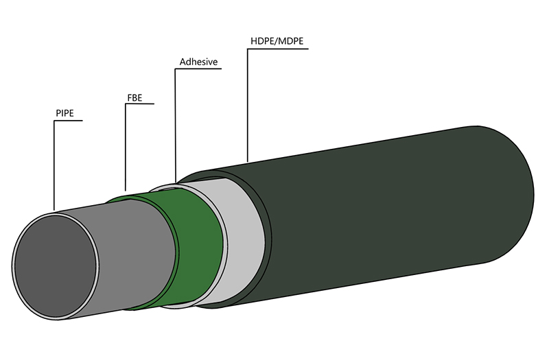
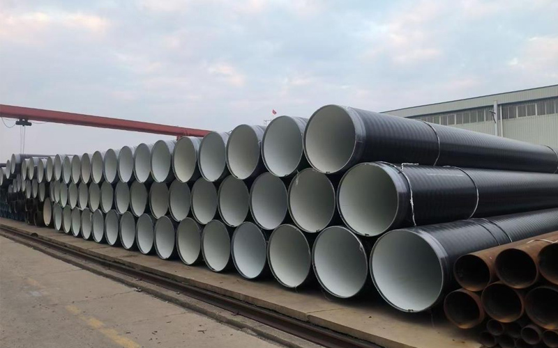
3LPE coated steel pipe: a solid barrier in the field of industrial corrosion protection
In the harsh environment of oil and gas, chemical industry, urban pipe network, etc., the long-term reliability and corrosion resistance of pipeline system...
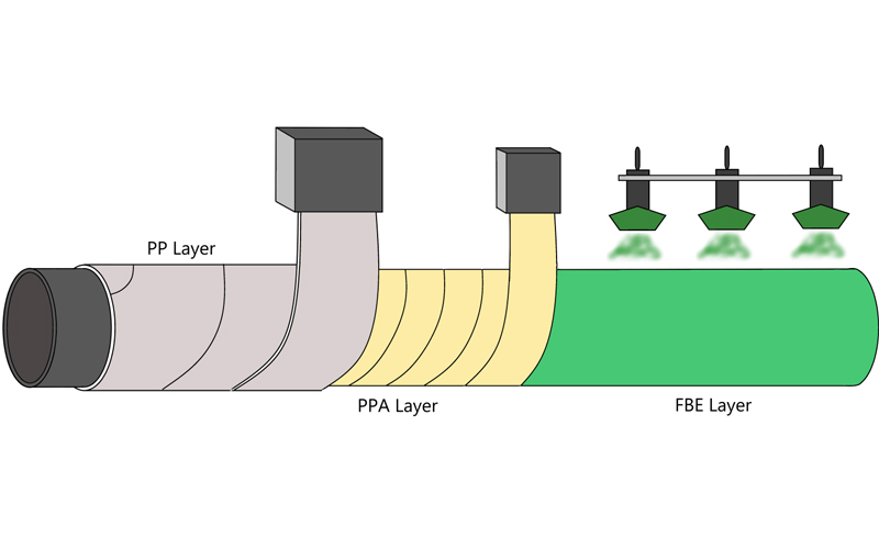
3LPP coated pipe: anti-corrosion guard in high temperature and high pressure environment
In some challenging special environments such as deep-sea oil and gas exploration and high-temperature crude oil transportation, traditional anti-corrosion coatings face significant challenges,...
FBE steel pipe: the technological armor of the steel defense line
I In the icy waters beneath the Norwegian Sea pipeline, a section of FBE Lined Carbon Steel Pipe has been in service for 25...