


·Standard: ANSI / UL 213C, EN 1092 ISO
·Material: Ductile iron
·Flanged end:
EN 1092-2, PN10 / PN 16 / PN 25,
RF or ANSI B16.1 Class 125,
B16.42 Class 150, FF or RF
·Rated pressure: 300 – 500 psi
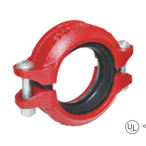
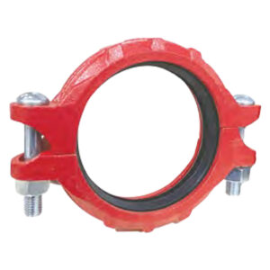
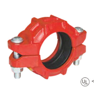
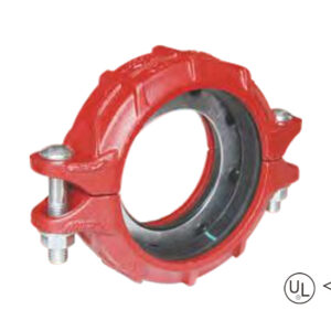
·Surface: Red or blue painting
·Size range: 3″ – 24″
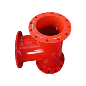
description
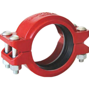
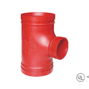
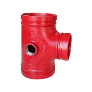
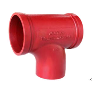
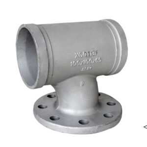
Flanged reducing tee is a reducing tee fitting with flange connection structure. The three interface sizes are different, and the branch connection of pipelines of different diameters is achieved through flange connection.
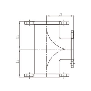
Specification
Available size
Size | Center to end (mm) | |||
Inch | DN | mm | L1 | L2 |
4″ × 3″ | 100 × 80 | 114.3 × 88.9 | 180 | 175 |
6″ × 3″ | 150 × 80 | 165.1 × 88.9 | 220 | 205 |
6″ × 4″ | 150 × 100 | 165.1 × 114.3 | 220 | 210 |
8″ × 3″ | 200 × 80 | 219.1 × 88.9 | 260 | 235 |
8″ × 4″ | 200 × 100 | 219.1 × 114.3 | 260 | 240 |
8″ × 6″ | 200 × 150 | 219.1 × 165.1 | 260 | 250 |
10″ × 4″ | 250 × 100 | 273.0 × 114.3 | 350 | 275 |
10″ × 6″ | 250 × 150 | 273.0 × 165.1 | 350 | 300 |
10″ × 8″ | 250 × 200 | 273.0 × 219.1 | 350 | 325 |
12″ × 4″ | 300 × 100 | 323.9 × 114.3 | 400 | 300 |
12″ × 6″ | 300 × 150 | 323.9 × 165.1 | 400 | 325 |
12″ × 8″ | 300 × 200 | 323.9 × 219.1 | 400 | 350 |
14″ × 4″ | 350 × 100 | 355.6 × 114.3 | 425 | 325 |
14″ × 6″ | 350 × 150 | 355.6 × 165.1 | 425 | 325 |
14″ × 8″ | 350 × 200 | 355.6 × 219.1 | 425 | 325 |
14″ × 12″ | 350 × 300 | 355.6 × 323.9 | 425 | 425 |
16″ × 4″ | 400 × 100 | 406.4 × 114.3 | 450 | 350 |
16″ × 6″ | 400 × 150 | 406.4 × 165.1 | 450 | 350 |
16″ × 8″ | 400 × 200 | 406.4 × 219.1 | 450 | 350 |
16″ × 12″ | 400 × 300 | 406.4 × 323.9 | 450 | 450 |
18″ × 4″ | 450 × 100 | 457.2 × 114.3 | 475 | 375 |
18″ × 6″ | 450 × 150 | 457.2 × 165.1 | 475 | 375 |
18″ × 8″ | 450 × 200 | 457.2 × 219.1 | 475 | 375 |
18″ × 12″ | 450 × 300 | 457.2 × 323.9 | 475 | 475 |
18″ × 16″ | 450 × 400 | 457.2 × 406.4 | 475 | 475 |
20″ × 4″ | 500 × 100 | 508.0 × 114.3 | 500 | 400 |
20″ × 6″ | 500 × 150 | 508.0 × 165.1 | 500 | 400 |
20″ × 8″ | 500 × 200 | 508.0 × 219.1 | 500 | 400 |
20″ × 12″ | 500 × 300 | 508.0 × 323.9 | 500 | 500 |
20″ × 16″ | 500 × 400 | 508.0 × 406.4 | 500 | 500 |
24″ × 6″ | 600 × 150 | 609.6 × 165.1 | 550 | 450 |
24″ × 8″ | 600 × 200 | 609.6 × 219.1 | 550 | 450 |
24″ × 12″ | 600 × 300 | 609.6 × 323.9 | 550 | 550 |
24″ × 16″ | 600 × 400 | 609.6 × 406.4 | 550 | 550 |
application
advantages
1. High Pressure Compatibility: Cast one-piece ductile iron, ANSI/EN/ISO certified rated to 300-500 psi with a high resistance to water hammer and pressure shocks.
2. Advanced mismatch adaptation: three-port diameter difference design, no turbulence energy loss into the tube cross-section, to improve the efficiency of the entire system;
3. Flange compatibility worldwide:American standard: ANSI Class 150 (RF/FF). European Standard: EN PN10/16/25 (RF). Able to serve project needs across regions
4. Corrosion protection: Red/blue epoxy coerce with excellent chemical corrosion resistance, made outdoor life much longer.
5. Full size combination to meet industrial level raw water transition requirements:4”×3”to 24”×16”(DN100-DN600).
packing
Available size
Size | Center to end (mm) | |||
Inch | DN | mm | L1 | L2 |
4″ × 3″ | 100 × 80 | 114.3 × 88.9 | 180 | 175 |
6″ × 3″ | 150 × 80 | 165.1 × 88.9 | 220 | 205 |
6″ × 4″ | 150 × 100 | 165.1 × 114.3 | 220 | 210 |
8″ × 3″ | 200 × 80 | 219.1 × 88.9 | 260 | 235 |
8″ × 4″ | 200 × 100 | 219.1 × 114.3 | 260 | 240 |
8″ × 6″ | 200 × 150 | 219.1 × 165.1 | 260 | 250 |
10″ × 4″ | 250 × 100 | 273.0 × 114.3 | 350 | 275 |
10″ × 6″ | 250 × 150 | 273.0 × 165.1 | 350 | 300 |
10″ × 8″ | 250 × 200 | 273.0 × 219.1 | 350 | 325 |
12″ × 4″ | 300 × 100 | 323.9 × 114.3 | 400 | 300 |
12″ × 6″ | 300 × 150 | 323.9 × 165.1 | 400 | 325 |
12″ × 8″ | 300 × 200 | 323.9 × 219.1 | 400 | 350 |
14″ × 4″ | 350 × 100 | 355.6 × 114.3 | 425 | 325 |
14″ × 6″ | 350 × 150 | 355.6 × 165.1 | 425 | 325 |
14″ × 8″ | 350 × 200 | 355.6 × 219.1 | 425 | 325 |
14″ × 12″ | 350 × 300 | 355.6 × 323.9 | 425 | 425 |
16″ × 4″ | 400 × 100 | 406.4 × 114.3 | 450 | 350 |
16″ × 6″ | 400 × 150 | 406.4 × 165.1 | 450 | 350 |
16″ × 8″ | 400 × 200 | 406.4 × 219.1 | 450 | 350 |
16″ × 12″ | 400 × 300 | 406.4 × 323.9 | 450 | 450 |
18″ × 4″ | 450 × 100 | 457.2 × 114.3 | 475 | 375 |
18″ × 6″ | 450 × 150 | 457.2 × 165.1 | 475 | 375 |
18″ × 8″ | 450 × 200 | 457.2 × 219.1 | 475 | 375 |
18″ × 12″ | 450 × 300 | 457.2 × 323.9 | 475 | 475 |
18″ × 16″ | 450 × 400 | 457.2 × 406.4 | 475 | 475 |
20″ × 4″ | 500 × 100 | 508.0 × 114.3 | 500 | 400 |
20″ × 6″ | 500 × 150 | 508.0 × 165.1 | 500 | 400 |
20″ × 8″ | 500 × 200 | 508.0 × 219.1 | 500 | 400 |
20″ × 12″ | 500 × 300 | 508.0 × 323.9 | 500 | 500 |
20″ × 16″ | 500 × 400 | 508.0 × 406.4 | 500 | 500 |
24″ × 6″ | 600 × 150 | 609.6 × 165.1 | 550 | 450 |
24″ × 8″ | 600 × 200 | 609.6 × 219.1 | 550 | 450 |
24″ × 12″ | 600 × 300 | 609.6 × 323.9 | 550 | 550 |
24″ × 16″ | 600 × 400 | 609.6 × 406.4 | 550 | 550 |
1. High Pressure Compatibility: Cast one-piece ductile iron, ANSI/EN/ISO certified rated to 300-500 psi with a high resistance to water hammer and pressure shocks.
2. Advanced mismatch adaptation: three-port diameter difference design, no turbulence energy loss into the tube cross-section, to improve the efficiency of the entire system;
3. Flange compatibility worldwide:American standard: ANSI Class 150 (RF/FF). European Standard: EN PN10/16/25 (RF). Able to serve project needs across regions
4. Corrosion protection: Red/blue epoxy coerce with excellent chemical corrosion resistance, made outdoor life much longer.
5. Full size combination to meet industrial level raw water transition requirements:4”×3”to 24”×16”(DN100-DN600).
Provide us with your project details (like application, specifications, quantity). Our experienced team will respond with a tailored solution and competitive quote within 24 business hours.
Grooved-increasing-tee-1-300x300.jpg)
We remain steadfast in our mission, driving innovation to deliver exceptional products and services for clients, empower employees with trans-formative growth opportunities, and create sustainable value for society.


