


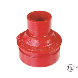
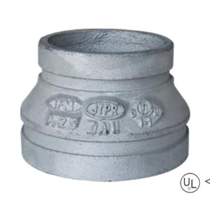
·Standard: ANSI / UL 213C UL / FM
·Material: Ductile iron ASTM A536, 65-45-12
·Rated pressure: 300 – 500 psi
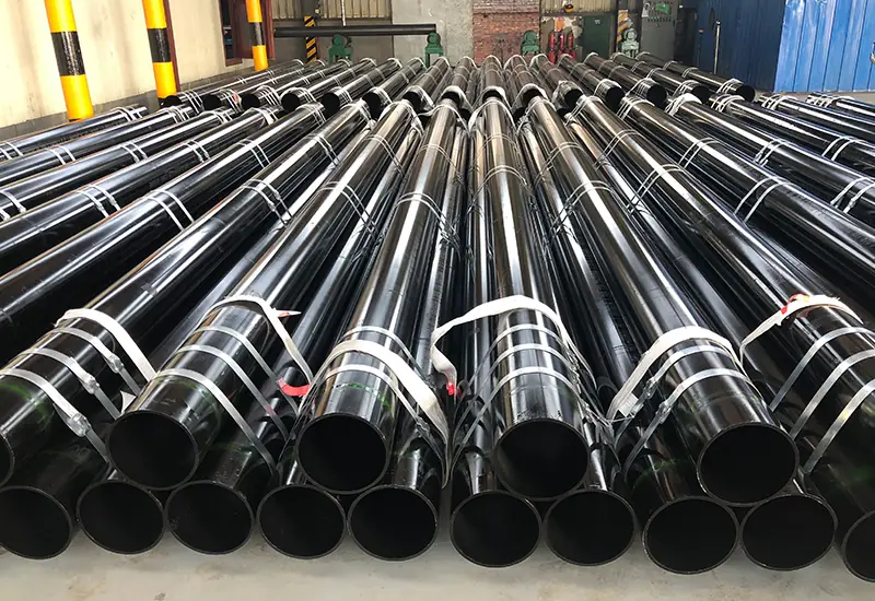
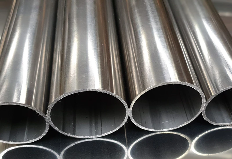
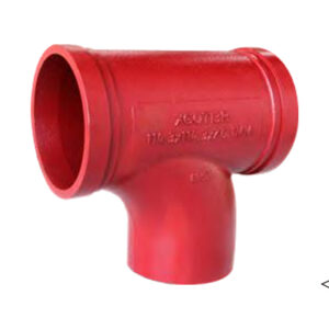
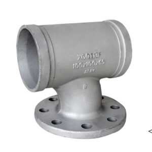
·Surface: Red painting / hot dip galvanized
·Size range: 1-1/4″×1″ – 12″×10″
description
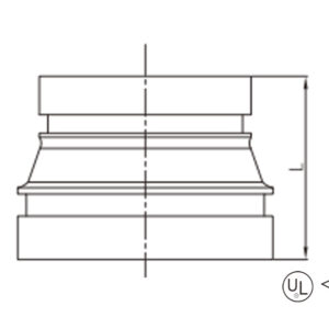
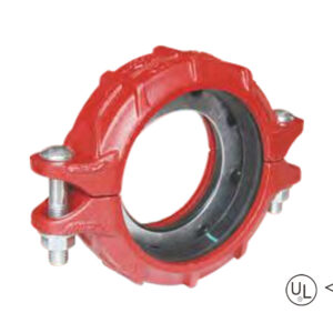
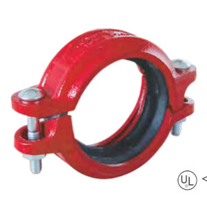
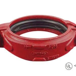
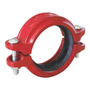
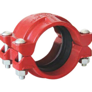
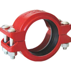
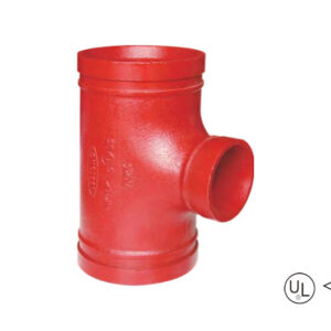
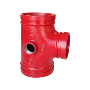
Grooved concentric reducer is a concentric reducer fitting. The diameters at both ends are different and the centerlines coincide. It is used to join pipes of different diameters by groove connection
Specification
Available size
Size | Center to end | ||
Inch | DN | mm | L(mm) |
1-1/4″ × 1″ | 32 × 25 | 42.4 × 33.7 | 64 |
1-1/2″ × 1″ | 40 × 25 | 48.3 × 33.7 | 64 |
1-1/2″ × 1-1/4″ | 40 × 32 | 48.3 × 42.4 | 64 |
2″ × 1″ | 50 × 25 | 60.3 × 33.7 | 64 |
2″ × 1-1/4″ | 50 × 32 | 60.3 × 42.4 | 64 |
2″ × 1-1/2″ | 50 × 40 | 60.3 × 48.3 | 64 |
2-1/2″ × 1″ | 65 × 25 | 73.0 × 33.7 | 64 |
2-1/2″ × 1-1/4″ | 65 × 32 | 73.0 × 42.4 | 64 |
2-1/2″ × 1-1/2″ | 65 × 40 | 73.0 × 48.3 | 64 |
2-1/2″ × 2″ | 65 × 50 | 73.0 × 60.3 | 64 |
2-1/2″ × 1″ | 65 × 25 | 76.1 × 33.7 | 64 |
2-1/2″ × 1-1/4″ | 65 × 32 | 76.1 × 42.4 | 64 |
2-1/2″ × 1-1/2″ | 65 × 40 | 76.1 × 48.3 | 64 |
2-1/2″ × 2″ | 65 × 50 | 76.1 × 60.3 | 64 |
3″ × 1″ | 80 × 25 | 88.9 × 33.7 | 64 |
3″ × 1-1/4″ | 80 × 32 | 88.9 × 42.4 | 64 |
3″ × 1-1/2″ | 80 × 40 | 88.9 × 48.3 | 64 |
3″ × 2″ | 80 × 50 | 88.9 × 60.3 | 64 |
3″ × 2-1/2″ | 80 × 65 | 88.9 × 73.0 | 64 |
3″ × 2-1/2″ | 80 × 65 | 88.9 × 76.1 | 64 |
4″ × 1-1/4″ | 100 × 32 | 114.3 × 42.4 | 76 |
4″ × 1-1/2″ | 100 × 40 | 114.3 × 48.3 | 76 |
4″ × 2″ | 100 × 50 | 114.3 × 60.3 | 76 |
4″ × 2-1/2″ | 100 × 65 | 114.3 × 73.0 | 76 |
4″ × 2-1/2″ | 100 × 65 | 114.3 × 76.1 | 76 |
4″ × 3″ | 100 × 80 | 114.3 × 88.9 | 76 |
5″ × 2″ | 125 × 50 | 139.7 × 60.3 | 89 |
5″ × 2-1/2″ | 125 × 65 | 139.7 × 76.1 | 89 |
5″ × 3″ | 125 × 80 | 139.7 × 88.9 | 89 |
5″ × 4″ | 125 × 100 | 139.7 × 114.3 | 89 |
5″ × 2-1/2″ | 125 × 65 | 141.3 × 73.0 | 89 |
5″ × 3″ | 125 × 80 | 141.3 × 88.9 | 89 |
5″ × 4″ | 125 × 100 | 141.3 × 114.3 | 89 |
6″ × 2″ | 150 × 50 | 165.1 × 60.3 | 102 |
6″ × 2-1/2″ | 150 × 65 | 165.1 × 76.1 | 102 |
6″ × 3″ | 150 × 80 | 165.1 × 88.9 | 102 |
6″ × 4″ | 150 × 100 | 165.1 × 114.3 | 102 |
6″ × 5″ | 150 × 125 | 165.1 × 139.7 | 102 |
6″ × 2″ | 150 × 50 | 168.3 × 60.3 | 102 |
6″ × 2-1/2″ | 150 × 65 | 168.3 × 73.0 | 102 |
6″ × 2-1/2″ | 150 × 65 | 168.3 × 76.1 | 102 |
6″ × 3″ | 150 × 80 | 168.3 × 88.9 | 102 |
6″ × 4″ | 150 × 100 | 168.3 × 114.3 | 102 |
6″ × 5″ | 150 × 125 | 168.3 × 139.7 | 102 |
6″ × 5″ | 150 × 125 | 168.3 × 141.3 | 102 |
8″ × 2″ | 200 × 50 | 219.1 × 60.3 | 127 |
8″ × 2-1/2″ | 200 × 65 | 219.1 × 73.0 | 127 |
8″ × 2-1/2″ | 200 × 65 | 219.1 × 76.1 | 127 |
8″ × 3″ | 200 × 80 | 219.1 × 88.9 | 127 |
8″ × 4″ | 200 × 100 | 219.1 × 114.3 | 127 |
8″ × 5″ | 200 × 125 | 219.1 × 139.7 | 127 |
8″ × 5″ | 200 × 125 | 219.1 × 141.3 | 127 |
8″ × 6″ | 200 × 150 | 219.1 × 165.1 | 127 |
8″ × 6″ | 200 × 150 | 219.1 × 168.3 | 127 |
10″ × 4″ | 250 × 100 | 273.0 × 114.3 | 152 |
10″ × 6″ | 250 × 150 | 273.0 × 165.1 | 152 |
10″ × 6″ | 250 × 150 | 273.0 × 168.3 | 152 |
10″ × 8″ | 250 × 200 | 273.0 × 219.1 | 152 |
12″ × 6″ | 300 × 150 | 323.9 × 165.1 | 178 |
12″ × 6″ | 300 × 150 | 323.9 × 168.3 | 178 |
12″ × 8″ | 300 × 200 | 323.9 × 219.1 | 178 |
12″ × 10″ | 300 × 250 | 323.9 × 273.0 | 178 |
application
advantages
1. Conical channel design zero resistance: The conical flow channels with concentric right angles reduce the fluid from the large pipe to the small pipe, so that all parts of the conduction become more smooth and smooth, which can reduce 40% loss;
2. Grooved clamp connections, equipping with UL/FM certification, are able to bear 300-500psi pressure and resist water hammer effects, which is suited for seismic resistant and maintenance-free;
3. Installing Minutes: Double-grooved end design eliminates the need for alignment calibration and installation speeds are up to three times faster than flanged connections;
4. Extraordinary Environmental Adaptation: Cast Iron Body (ASTM A536) with red paint/hot dig galv coating, immune to chemical rust in addition to temperatures changes -30 °C to 150 °C.
packing
Available size
Size | Center to end | ||
Inch | DN | mm | L(mm) |
1-1/4″ × 1″ | 32 × 25 | 42.4 × 33.7 | 64 |
1-1/2″ × 1″ | 40 × 25 | 48.3 × 33.7 | 64 |
1-1/2″ × 1-1/4″ | 40 × 32 | 48.3 × 42.4 | 64 |
2″ × 1″ | 50 × 25 | 60.3 × 33.7 | 64 |
2″ × 1-1/4″ | 50 × 32 | 60.3 × 42.4 | 64 |
2″ × 1-1/2″ | 50 × 40 | 60.3 × 48.3 | 64 |
2-1/2″ × 1″ | 65 × 25 | 73.0 × 33.7 | 64 |
2-1/2″ × 1-1/4″ | 65 × 32 | 73.0 × 42.4 | 64 |
2-1/2″ × 1-1/2″ | 65 × 40 | 73.0 × 48.3 | 64 |
2-1/2″ × 2″ | 65 × 50 | 73.0 × 60.3 | 64 |
2-1/2″ × 1″ | 65 × 25 | 76.1 × 33.7 | 64 |
2-1/2″ × 1-1/4″ | 65 × 32 | 76.1 × 42.4 | 64 |
2-1/2″ × 1-1/2″ | 65 × 40 | 76.1 × 48.3 | 64 |
2-1/2″ × 2″ | 65 × 50 | 76.1 × 60.3 | 64 |
3″ × 1″ | 80 × 25 | 88.9 × 33.7 | 64 |
3″ × 1-1/4″ | 80 × 32 | 88.9 × 42.4 | 64 |
3″ × 1-1/2″ | 80 × 40 | 88.9 × 48.3 | 64 |
3″ × 2″ | 80 × 50 | 88.9 × 60.3 | 64 |
3″ × 2-1/2″ | 80 × 65 | 88.9 × 73.0 | 64 |
3″ × 2-1/2″ | 80 × 65 | 88.9 × 76.1 | 64 |
4″ × 1-1/4″ | 100 × 32 | 114.3 × 42.4 | 76 |
4″ × 1-1/2″ | 100 × 40 | 114.3 × 48.3 | 76 |
4″ × 2″ | 100 × 50 | 114.3 × 60.3 | 76 |
4″ × 2-1/2″ | 100 × 65 | 114.3 × 73.0 | 76 |
4″ × 2-1/2″ | 100 × 65 | 114.3 × 76.1 | 76 |
4″ × 3″ | 100 × 80 | 114.3 × 88.9 | 76 |
5″ × 2″ | 125 × 50 | 139.7 × 60.3 | 89 |
5″ × 2-1/2″ | 125 × 65 | 139.7 × 76.1 | 89 |
5″ × 3″ | 125 × 80 | 139.7 × 88.9 | 89 |
5″ × 4″ | 125 × 100 | 139.7 × 114.3 | 89 |
5″ × 2-1/2″ | 125 × 65 | 141.3 × 73.0 | 89 |
5″ × 3″ | 125 × 80 | 141.3 × 88.9 | 89 |
5″ × 4″ | 125 × 100 | 141.3 × 114.3 | 89 |
6″ × 2″ | 150 × 50 | 165.1 × 60.3 | 102 |
6″ × 2-1/2″ | 150 × 65 | 165.1 × 76.1 | 102 |
6″ × 3″ | 150 × 80 | 165.1 × 88.9 | 102 |
6″ × 4″ | 150 × 100 | 165.1 × 114.3 | 102 |
6″ × 5″ | 150 × 125 | 165.1 × 139.7 | 102 |
6″ × 2″ | 150 × 50 | 168.3 × 60.3 | 102 |
6″ × 2-1/2″ | 150 × 65 | 168.3 × 73.0 | 102 |
6″ × 2-1/2″ | 150 × 65 | 168.3 × 76.1 | 102 |
6″ × 3″ | 150 × 80 | 168.3 × 88.9 | 102 |
6″ × 4″ | 150 × 100 | 168.3 × 114.3 | 102 |
6″ × 5″ | 150 × 125 | 168.3 × 139.7 | 102 |
6″ × 5″ | 150 × 125 | 168.3 × 141.3 | 102 |
8″ × 2″ | 200 × 50 | 219.1 × 60.3 | 127 |
8″ × 2-1/2″ | 200 × 65 | 219.1 × 73.0 | 127 |
8″ × 2-1/2″ | 200 × 65 | 219.1 × 76.1 | 127 |
8″ × 3″ | 200 × 80 | 219.1 × 88.9 | 127 |
8″ × 4″ | 200 × 100 | 219.1 × 114.3 | 127 |
8″ × 5″ | 200 × 125 | 219.1 × 139.7 | 127 |
8″ × 5″ | 200 × 125 | 219.1 × 141.3 | 127 |
8″ × 6″ | 200 × 150 | 219.1 × 165.1 | 127 |
8″ × 6″ | 200 × 150 | 219.1 × 168.3 | 127 |
10″ × 4″ | 250 × 100 | 273.0 × 114.3 | 152 |
10″ × 6″ | 250 × 150 | 273.0 × 165.1 | 152 |
10″ × 6″ | 250 × 150 | 273.0 × 168.3 | 152 |
10″ × 8″ | 250 × 200 | 273.0 × 219.1 | 152 |
12″ × 6″ | 300 × 150 | 323.9 × 165.1 | 178 |
12″ × 6″ | 300 × 150 | 323.9 × 168.3 | 178 |
12″ × 8″ | 300 × 200 | 323.9 × 219.1 | 178 |
12″ × 10″ | 300 × 250 | 323.9 × 273.0 | 178 |
1. Conical channel design zero resistance: The conical flow channels with concentric right angles reduce the fluid from the large pipe to the small pipe, so that all parts of the conduction become more smooth and smooth, which can reduce 40% loss;
2. Grooved clamp connections, equipping with UL/FM certification, are able to bear 300-500psi pressure and resist water hammer effects, which is suited for seismic resistant and maintenance-free;
3. Installing Minutes: Double-grooved end design eliminates the need for alignment calibration and installation speeds are up to three times faster than flanged connections;
4. Extraordinary Environmental Adaptation: Cast Iron Body (ASTM A536) with red paint/hot dig galv coating, immune to chemical rust in addition to temperatures changes -30 °C to 150 °C.
Provide us with your project details (like application, specifications, quantity). Our experienced team will respond with a tailored solution and competitive quote within 24 business hours.
Grooved-increasing-tee-1-300x300.jpg)
We remain steadfast in our mission, driving innovation to deliver exceptional products and services for clients, empower employees with trans-formative growth opportunities, and create sustainable value for society.

