


Grooved-increasing-tee-1.jpg "grooved increasing tee")
Grooved-increasing-tee-2.jpg "grooved increasing tee")
Grooved-increasing-tee-3.jpg "grooved increasing tee")
Grooved-increasing-tee-1-300x300.jpg)
Grooved-increasing-tee-2-300x300.jpg)
Grooved-increasing-tee-3-300x300.jpg)
·Standard: ANSI / UL 213C UL / FM
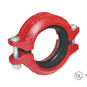
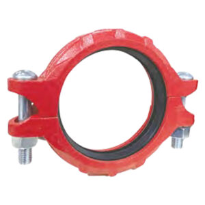
·Material: Ductile iron ASTM A536, 65-45-12
·Rated pressure: 300 – 500 psi
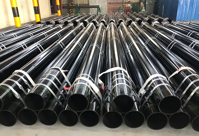
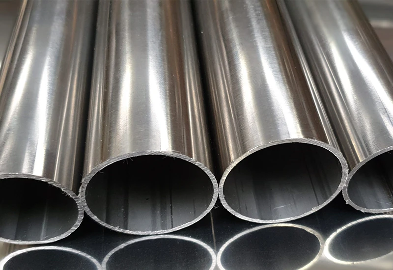
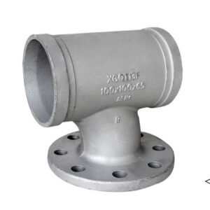
·Surface: Black / red painting / hot dip galvanized
·Size range: 3”×3”×4” – 4”×4”×6′
description
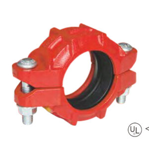
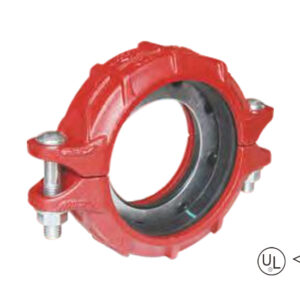
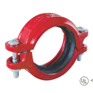
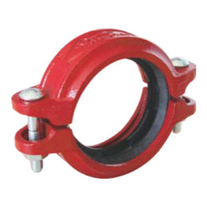
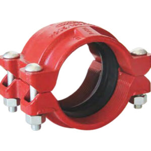
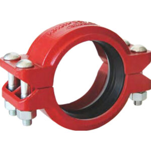
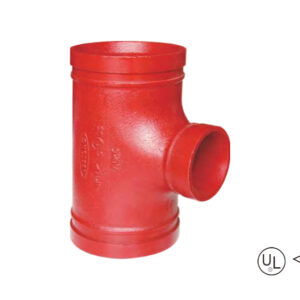
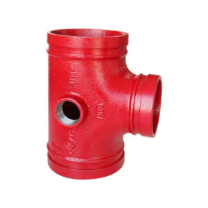
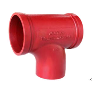
Grooved increasing tee is a reducer tee fitting with a grooved connection structure, where the diameter of the branch joint is larger than that of the main pipe joint. It is used in piping systems to achieve vertical branch connections with increased pipe diameters.
Specification
Available size
Size | Center to end(mm) | |||
Inch | DN | mm | L1 | L2 |
3” × 3” × 4” | 80 × 80 × 100 | 88.9 × 88.9 × 114.3 | 115 | 130 |
3” × 3” × 6” | 80 × 80 × 150 | 88.9 × 88.9 × 165.1 | 140 | 140 |
4” × 4” × 6” | 100 × 100 × 150 | 114.3 × 114.3 × 165.1 | 140 | 140 |
application
advantages
1. Performance Engineers flow enhancement was very successful, a redesign with branch pipe enlargement of the top-located outlet decreased fluid resistance and improved branch pipe transportation efficiency.
2. Mechanical Strength and Impact Resistance: Ductile iron material, ASTM A536.
3. Quick Install — No welding required; seal assembly requires only tightening bolts and clamps.
4. Various Safeguards:Wrap in black paint and hot dip galvanization to be waterproof, moisture resistance and swelling resistance.
5. Certification Assurance: ANSI/UL/FM Listed for Pressure 300 to 500 psi.
packing
Available size
Size | Center to end(mm) | |||
Inch | DN | mm | L1 | L2 |
3” × 3” × 4” | 80 × 80 × 100 | 88.9 × 88.9 × 114.3 | 115 | 130 |
3” × 3” × 6” | 80 × 80 × 150 | 88.9 × 88.9 × 165.1 | 140 | 140 |
4” × 4” × 6” | 100 × 100 × 150 | 114.3 × 114.3 × 165.1 | 140 | 140 |
1. Performance Engineers flow enhancement was very successful, a redesign with branch pipe enlargement of the top-located outlet decreased fluid resistance and improved branch pipe transportation efficiency.
2. Mechanical Strength and Impact Resistance: Ductile iron material, ASTM A536.
3. Quick Install — No welding required; seal assembly requires only tightening bolts and clamps.
4. Various Safeguards:Wrap in black paint and hot dip galvanization to be waterproof, moisture resistance and swelling resistance.
5. Certification Assurance: ANSI/UL/FM Listed for Pressure 300 to 500 psi.
Provide us with your project details (like application, specifications, quantity). Our experienced team will respond with a tailored solution and competitive quote within 24 business hours.
We remain steadfast in our mission, driving innovation to deliver exceptional products and services for clients, empower employees with trans-formative growth opportunities, and create sustainable value for society.


