


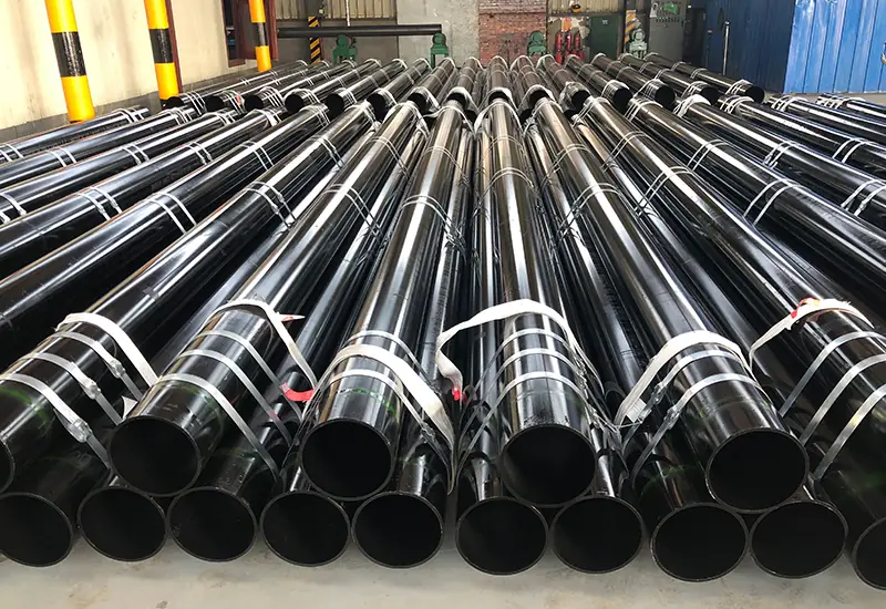


The tube body of the high pressure steel pipe is the most complicated and most weak link in the manufacturing, and the welding seam is of the highest precision and the weakest length in the product. The quality of that single metallurgical bond which makes up a pipe´s long seam, is the key to a pipe´s ability to stand up to decades of pressure, the elements and operating wear and tear. The weld looks great on the outside, but lies inexorably within the steel. So how do manufacturers reveal this hidden world? They can use a variety of sophisticated inspection methods collectively referred to as Non-Destructive Testing (NDT).
Read more NDT makes it possible for us to peer inside the weld without cutting or otherwise destroying the pipe, offering an essential window into the flowline’s internal configuration. The two of the most powerful NDT techniques, frequently used in the pipe production, are Radiographic Testing (RT) – called also as X-ray – and Ultrasonic Testing (UT). Ok, they both were implemented to eradicated a flawed welding line, but these are entirely different operating principles and for detecting different types of faults. Whether you work as an engineer, an inspector, or a procurement manager, it’s important to understand the functions and distinctions of X-ray versus UT to be able to understand what it means to have a quality-assured steel pipe.
What is Non-Destructive Testing (NDT)?
Overview Non-Destructive Testing (NDT) comprises a variety of analysis techniques which are used in science and industry to evaluate and examine material or component properties as respect integrity without causing any damage. In the steel pipe production process, NDT is applied to the weld seam to detect internal and surface-breaking defects, which may affect the integrity of the weld.
Whereas a tensile or impact test requires the destruction of a piece in which one is interested to verify material properties, NDT is done on 100% of the finished product. It isn’t a sample test, it is an exhaustive test of every square millimetre of the weld. The aim is to identify and categorize defects, such as cracks, porosity, inclusions, and lack of penetration. It is only through strict observance of a stringent NDT regime (such as that specified by the various standards such as API 5L) that it can be ensured that all pipes leaving the factory are free of serious flaws.
Radiographic Testing (RT / X-ray): A Look Inside
Radiographic Testing (RT) operates on a concept that is similar to a medical X-ray. It is achieved by employing a source of penetrating rays (an X-ray tube or a gamma-ray source such as Iridium-192) which traverse the weld seam. The opposite side of the weld is detected by, typically, dedicated photographic film or digital camera based detectors.
The radiation is absorbed to different extents depending on the density and thickness of the material as it passes through the pipe. Much of the radiation will be attenuated by the sound base metal and weld material. But, if the weld contains a flaw, like a gas pore (a void) or a slag (nonmetallic inclusion), that region will have less dense material. The detector will be exposed to more radiation that passes through this less-dense area. The result is a 2D shadow picture or radiograph that represents a visual map of the weld’s internal structure that can be retained permanently. The denser photo speaks lighter” into the film and less dense (the defects) appear darker.
Strengths of Radiographic Testing: Finding Volumetric Flaws
Because RT is fundamentally a density-mapping technique, it is exceptionally good at finding volumetric defects. These are flaws that have a measurable height, width, and depth. Key examples include:
· Porosity: Small, often spherical voids or gas pockets trapped within the weld metal. They appear as small, dark, round spots on the radiograph.
· Slag Inclusions: Non-metallic solids trapped in the weld, which are less dense than the steel. They typically appear as elongated or irregularly shaped dark indications.
· Incomplete Penetration: A condition where the weld metal fails to fuse completely with the root of the joint, leaving a void. This appears as a dark, continuous line along the center of the weld image.
The primary limitation of RT is its reduced sensitivity to planar defects, most notably cracks. A crack is a very thin, tight flaw. Unless the radiation beam is aligned almost perfectly parallel to the crack, the change in density is too small to be reliably detected on the radiograph.
Ultrasonic Testing (UT): Listening for Echoes
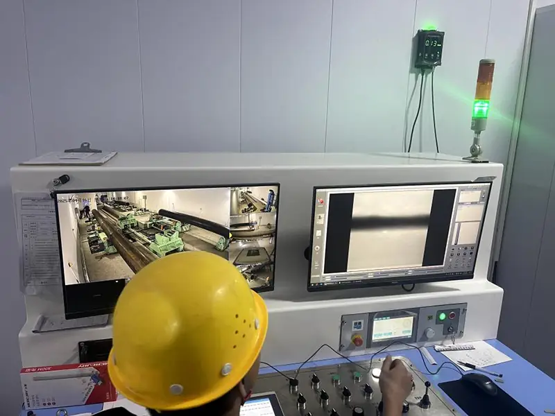
Ultrasonic Testing operates on a completely different principle: acoustics. It uses high-frequency sound waves, far beyond the range of human hearing, to inspect the material. A small probe, called a transducer, is placed on the surface of the pipe. The transducer, containing a piezoelectric crystal, converts an electrical pulse into a mechanical vibration—a short burst of sound waves.
Those sound waves propagate through steel at a constant speed. When they meet a barrier, such as a rear wall of the pipe or an internal flaw, they reflect from it producing an echo. This echo returns to the transducer, and the ultrasonic sound wave is transformed into an electrical signal. This signal is subsequently output to the screen and viewed there as a point or segment on a time base (A-scan display). By interpreting the position and amplitude of these echoes, the operator is capable of determining the exact location, size, and orientation of any defect in the weld.
Strengths of Ultrasonic Testing: Detecting Critical Planar Flaws
As UT relies on sound reflection, it is very sensitive to any surface that intersect the sound path. The technique is the best one available for detecting planar defects, which are two-dimensional flaws that are commonly perceived as the most dangerous in that they can grow quickly under stress. Key examples include:
· Cracks:UT is the simplest way of crack detection. Even fine, minute cracks, being tight, will present a large reflecting area to the sound beam and finish then can present a very strong and sharp echo.
· Insufficient Fusion: A condition in which the weld metal does not properly fuse with the sidewall of the weld. This forms a planar reflector similar to a crack, which is readily detected by ultrasonic testing (UT).
· Laminations: These are portions of the steel plate itself that are separated from one another and can be detected by scanning the base material adjacent to the welded joint.
UT has the ability to detect volumetric defects, and to some extent the shape and composition of the defect, but not as readily as with an X-ray image and is very operator dependent. r.
A Head-to-Head Comparison: RT vs. UT
To summarize the core differences, the following table compares the key attributes of both NDT methods:
| Attribute | Radiographic Testing (X-ray) | Ultrasonic Testing (UT) |
| Primary Strength | Best for Volumetric Defects (porosity, slag) | Best for Planar Defects (cracks, lack of fusion) |
| Principle | Density differences via radiation absorption | Sound wave reflection from discontinuities |
| Speed & Efficiency | Slower; requires processing time for film | Faster; provides immediate, real-time results |
| Safety | Involves ionizing radiation; requires strict safety protocols | Safe; uses harmless sound waves |
| Data Format | Permanent, intuitive visual image (radiograph) | Electronic signal on a screen requiring skilled interpretation |
| Operator Skill | Requires certified interpreters to read film | Highly dependent on the skill of the certified operator |
Why a Dual-Method Approach is the Gold Standard
Previously, manufacturers may have argued over which approach was better. This is no longer the case and today the common view among high-end pipe makers is that RT and UT are no longer opposing technologies, but partners in a full QA program.
A thorough ITP following API 5L normally combines advantages of the two practices in order to reach the best defect determination. Here’s how one common workflow might play out:
1. UT – Automated Ultrasonic Testing The complete length of all weld seams is examined with an auto-mated UT-system. 100% of the production can be screened very quickly and efficiently for the most important planar flaws like cracks.
2. Radiographic Testing (RT): X-ray inspection is then performed on the ends of the pipe, which are the most vulnerable areas for field weld. This is also a secondary technique to further examine any suspect indications that were noted during the UT scan but provide a visual image to assist with defect characterization.
The speed and crack sensitivity of UT with the proof of WORK that RT gives them, mean that they can assure quality at an appropriate level that either method alone would not.
Conclusion: A Commitment to Comprehensive Quality
It’s not a case of one being better than the other, it’s a case of sometimes you need a screwdriver and sometimes you need a spanner. X-ray produces a permanent and readable “image” of the inside of the weld, which makes it highly effective for detecting volumetric defects. Ultrasonic testing serves as a pair of sensitive “ears,” in search of the echoes of very harmfuL planar defects (e.g., cracks). A world-class pipe manufacturer

ASTM A53 vs. API 5L: A Guide to Selection and Application
In the field of industrial piping, ASTM A53 and API 5L are two key standards that are widely used, but have very different positions. ASTM...

Introduction:Technology differences determine success or failure, and selection needs to be “precise”
In oil and gas transmission, municipal infrastructure and other major projects, the reasonable choice of steel pipe welding process directly affects the project...
Steel Density Analysis: Core Differences between Mild and Medium Carbon Steels and Industrial Applications
The density of steel is one of the key parameters that determine its physical properties and industrial applications. Theoretical state of steel density...
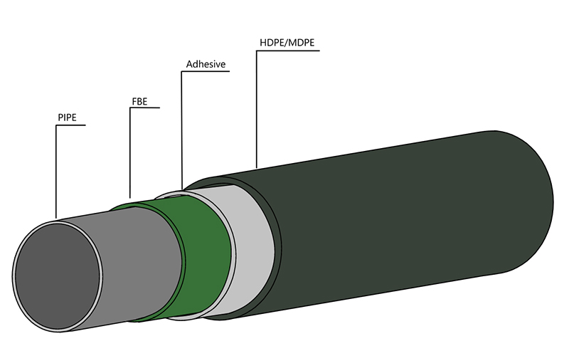
3LPE coated steel pipe: a solid barrier in the field of industrial corrosion protection
In the harsh environment of oil and gas, chemical industry, urban pipe network, etc., the long-term reliability and corrosion resistance of pipeline system...
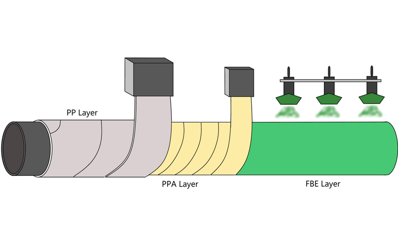
3LPP coated pipe: anti-corrosion guard in high temperature and high pressure environment
In some challenging special environments such as deep-sea oil and gas exploration and high-temperature crude oil transportation, traditional anti-corrosion coatings face significant challenges,...
FBE steel pipe: the technological armor of the steel defense line
I In the icy waters beneath the Norwegian Sea pipeline, a section of FBE Lined Carbon Steel Pipe has been in service for 25...