


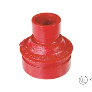
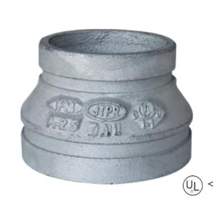
-Standard : ANSI / UL 213C UL / FM
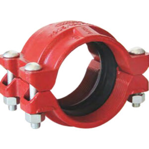
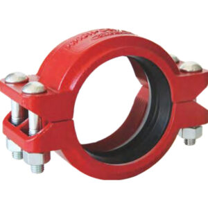
-Matériau : Fonte ductile ASTM A536, 65-45-12
-Pression nominale : 300 - 500 psi
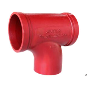
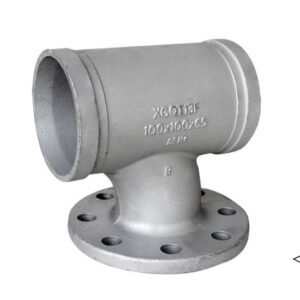
-Surface : Peinture rouge / galvanisation à chaud
-Gamme de tailles : 1-1/4″×1″ – 12″×10″
description
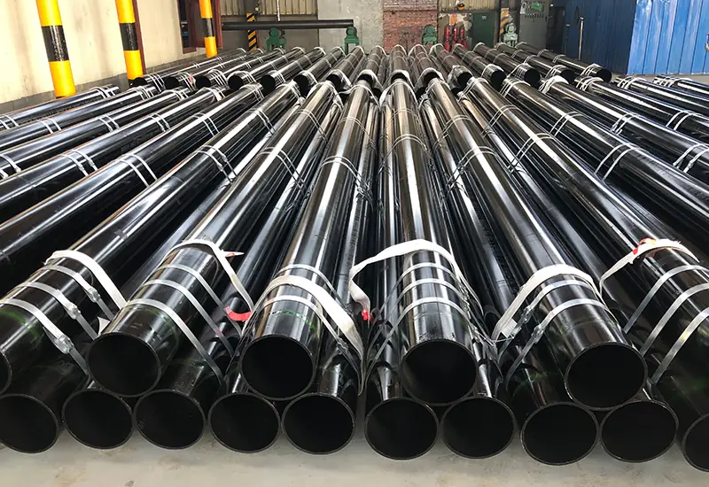
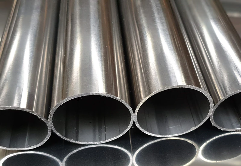
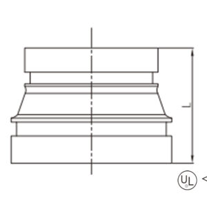
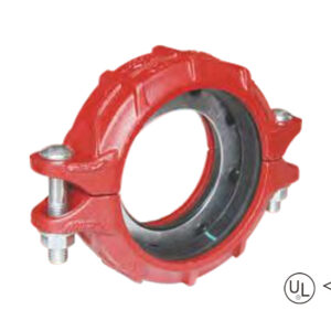
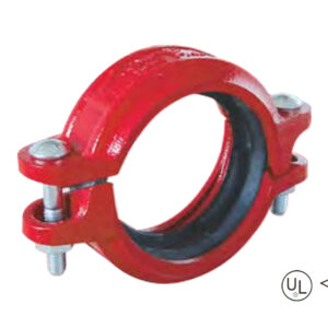
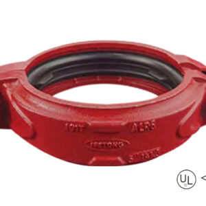
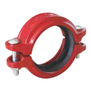
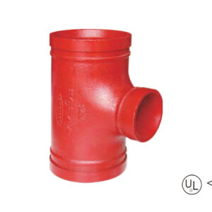
Grooved concentric reducer is a concentric reducer fitting. The diameters at both ends are different and the centerlines coincide. It is used to join pipes of different diameters by groove connection
Spécifications
Taille disponible
Taille | Du centre à la fin | ||
Pouce | DN | mm | L(mm) |
1-1/4″ × 1″ | 32 × 25 | 42.4 × 33.7 | 64 |
1-1/2″ × 1″ | 40 × 25 | 48.3 × 33.7 | 64 |
1-1/2″ × 1-1/4″ | 40 × 32 | 48.3 × 42.4 | 64 |
2″ × 1″ | 50 × 25 | 60.3 × 33.7 | 64 |
2″ × 1-1/4″ | 50 × 32 | 60.3 × 42.4 | 64 |
2″ × 1-1/2″ | 50 × 40 | 60.3 × 48.3 | 64 |
2-1/2″ × 1″ | 65 × 25 | 73.0 × 33.7 | 64 |
2-1/2″ × 1-1/4″ | 65 × 32 | 73.0 × 42.4 | 64 |
2-1/2″ × 1-1/2″ | 65 × 40 | 73.0 × 48.3 | 64 |
2-1/2″ × 2″ | 65 × 50 | 73.0 × 60.3 | 64 |
2-1/2″ × 1″ | 65 × 25 | 76.1 × 33.7 | 64 |
2-1/2″ × 1-1/4″ | 65 × 32 | 76.1 × 42.4 | 64 |
2-1/2″ × 1-1/2″ | 65 × 40 | 76.1 × 48.3 | 64 |
2-1/2″ × 2″ | 65 × 50 | 76.1 × 60.3 | 64 |
3″ × 1″ | 80 × 25 | 88.9 × 33.7 | 64 |
3″ × 1-1/4″ | 80 × 32 | 88.9 × 42.4 | 64 |
3″ × 1-1/2″ | 80 × 40 | 88.9 × 48.3 | 64 |
3″ × 2″ | 80 × 50 | 88.9 × 60.3 | 64 |
3″ × 2-1/2″ | 80 × 65 | 88.9 × 73.0 | 64 |
3″ × 2-1/2″ | 80 × 65 | 88.9 × 76.1 | 64 |
4″ × 1-1/4″ | 100 × 32 | 114.3 × 42.4 | 76 |
4″ × 1-1/2″ | 100 × 40 | 114.3 × 48.3 | 76 |
4″ × 2″ | 100 × 50 | 114.3 × 60.3 | 76 |
4″ × 2-1/2″ | 100 × 65 | 114.3 × 73.0 | 76 |
4″ × 2-1/2″ | 100 × 65 | 114.3 × 76.1 | 76 |
4″ × 3″ | 100 × 80 | 114.3 × 88.9 | 76 |
5″ × 2″ | 125 × 50 | 139.7 × 60.3 | 89 |
5″ × 2-1/2″ | 125 × 65 | 139.7 × 76.1 | 89 |
5″ × 3″ | 125 × 80 | 139.7 × 88.9 | 89 |
5″ × 4″ | 125 × 100 | 139.7 × 114.3 | 89 |
5″ × 2-1/2″ | 125 × 65 | 141.3 × 73.0 | 89 |
5″ × 3″ | 125 × 80 | 141.3 × 88.9 | 89 |
5″ × 4″ | 125 × 100 | 141.3 × 114.3 | 89 |
6″ × 2″ | 150 × 50 | 165.1 × 60.3 | 102 |
6″ × 2-1/2″ | 150 × 65 | 165.1 × 76.1 | 102 |
6″ × 3″ | 150 × 80 | 165.1 × 88.9 | 102 |
6″ × 4″ | 150 × 100 | 165.1 × 114.3 | 102 |
6″ × 5″ | 150 × 125 | 165.1 × 139.7 | 102 |
6″ × 2″ | 150 × 50 | 168.3 × 60.3 | 102 |
6″ × 2-1/2″ | 150 × 65 | 168.3 × 73.0 | 102 |
6″ × 2-1/2″ | 150 × 65 | 168.3 × 76.1 | 102 |
6″ × 3″ | 150 × 80 | 168.3 × 88.9 | 102 |
6″ × 4″ | 150 × 100 | 168.3 × 114.3 | 102 |
6″ × 5″ | 150 × 125 | 168.3 × 139.7 | 102 |
6″ × 5″ | 150 × 125 | 168.3 × 141.3 | 102 |
8″ × 2″ | 200 × 50 | 219.1 × 60.3 | 127 |
8″ × 2-1/2″ | 200 × 65 | 219.1 × 73.0 | 127 |
8″ × 2-1/2″ | 200 × 65 | 219.1 × 76.1 | 127 |
8″ × 3″ | 200 × 80 | 219.1 × 88.9 | 127 |
8″ × 4″ | 200 × 100 | 219.1 × 114.3 | 127 |
8″ × 5″ | 200 × 125 | 219.1 × 139.7 | 127 |
8″ × 5″ | 200 × 125 | 219.1 × 141.3 | 127 |
8″ × 6″ | 200 × 150 | 219.1 × 165.1 | 127 |
8″ × 6″ | 200 × 150 | 219.1 × 168.3 | 127 |
10″ × 4″ | 250 × 100 | 273.0 × 114.3 | 152 |
10″ × 6″ | 250 × 150 | 273.0 × 165.1 | 152 |
10″ × 6″ | 250 × 150 | 273.0 × 168.3 | 152 |
10″ × 8″ | 250 × 200 | 273.0 × 219.1 | 152 |
12″ × 6″ | 300 × 150 | 323.9 × 165.1 | 178 |
12″ × 6″ | 300 × 150 | 323.9 × 168.3 | 178 |
12″ × 8″ | 300 × 200 | 323.9 × 219.1 | 178 |
12″ × 10″ | 300 × 250 | 323.9 × 273.0 | 178 |
application
avantages
1. Conical channel design zero resistance: The conical flow channels with concentric right angles reduce the fluid from the large pipe to the small pipe, so that all parts of the conduction become more smooth and smooth, which can reduce 40% loss;
2. Grooved clamp connections, equipping with UL/FM certification, are able to bear 300-500psi pressure and resist water hammer effects, which is suited for seismic resistant and maintenance-free;
3. Installing Minutes: Double-grooved end design eliminates the need for alignment calibration and installation speeds are up to three times faster than flanged connections;
4. Extraordinary Environmental Adaptation: Cast Iron Body (ASTM A536) with red paint/hot dig galv coating, immune to chemical rust in addition to temperatures changes -30 °C to 150 °C.
emballage
Taille disponible
Taille | Du centre à la fin | ||
Pouce | DN | mm | L(mm) |
1-1/4″ × 1″ | 32 × 25 | 42.4 × 33.7 | 64 |
1-1/2″ × 1″ | 40 × 25 | 48.3 × 33.7 | 64 |
1-1/2″ × 1-1/4″ | 40 × 32 | 48.3 × 42.4 | 64 |
2″ × 1″ | 50 × 25 | 60.3 × 33.7 | 64 |
2″ × 1-1/4″ | 50 × 32 | 60.3 × 42.4 | 64 |
2″ × 1-1/2″ | 50 × 40 | 60.3 × 48.3 | 64 |
2-1/2″ × 1″ | 65 × 25 | 73.0 × 33.7 | 64 |
2-1/2″ × 1-1/4″ | 65 × 32 | 73.0 × 42.4 | 64 |
2-1/2″ × 1-1/2″ | 65 × 40 | 73.0 × 48.3 | 64 |
2-1/2″ × 2″ | 65 × 50 | 73.0 × 60.3 | 64 |
2-1/2″ × 1″ | 65 × 25 | 76.1 × 33.7 | 64 |
2-1/2″ × 1-1/4″ | 65 × 32 | 76.1 × 42.4 | 64 |
2-1/2″ × 1-1/2″ | 65 × 40 | 76.1 × 48.3 | 64 |
2-1/2″ × 2″ | 65 × 50 | 76.1 × 60.3 | 64 |
3″ × 1″ | 80 × 25 | 88.9 × 33.7 | 64 |
3″ × 1-1/4″ | 80 × 32 | 88.9 × 42.4 | 64 |
3″ × 1-1/2″ | 80 × 40 | 88.9 × 48.3 | 64 |
3″ × 2″ | 80 × 50 | 88.9 × 60.3 | 64 |
3″ × 2-1/2″ | 80 × 65 | 88.9 × 73.0 | 64 |
3″ × 2-1/2″ | 80 × 65 | 88.9 × 76.1 | 64 |
4″ × 1-1/4″ | 100 × 32 | 114.3 × 42.4 | 76 |
4″ × 1-1/2″ | 100 × 40 | 114.3 × 48.3 | 76 |
4″ × 2″ | 100 × 50 | 114.3 × 60.3 | 76 |
4″ × 2-1/2″ | 100 × 65 | 114.3 × 73.0 | 76 |
4″ × 2-1/2″ | 100 × 65 | 114.3 × 76.1 | 76 |
4″ × 3″ | 100 × 80 | 114.3 × 88.9 | 76 |
5″ × 2″ | 125 × 50 | 139.7 × 60.3 | 89 |
5″ × 2-1/2″ | 125 × 65 | 139.7 × 76.1 | 89 |
5″ × 3″ | 125 × 80 | 139.7 × 88.9 | 89 |
5″ × 4″ | 125 × 100 | 139.7 × 114.3 | 89 |
5″ × 2-1/2″ | 125 × 65 | 141.3 × 73.0 | 89 |
5″ × 3″ | 125 × 80 | 141.3 × 88.9 | 89 |
5″ × 4″ | 125 × 100 | 141.3 × 114.3 | 89 |
6″ × 2″ | 150 × 50 | 165.1 × 60.3 | 102 |
6″ × 2-1/2″ | 150 × 65 | 165.1 × 76.1 | 102 |
6″ × 3″ | 150 × 80 | 165.1 × 88.9 | 102 |
6″ × 4″ | 150 × 100 | 165.1 × 114.3 | 102 |
6″ × 5″ | 150 × 125 | 165.1 × 139.7 | 102 |
6″ × 2″ | 150 × 50 | 168.3 × 60.3 | 102 |
6″ × 2-1/2″ | 150 × 65 | 168.3 × 73.0 | 102 |
6″ × 2-1/2″ | 150 × 65 | 168.3 × 76.1 | 102 |
6″ × 3″ | 150 × 80 | 168.3 × 88.9 | 102 |
6″ × 4″ | 150 × 100 | 168.3 × 114.3 | 102 |
6″ × 5″ | 150 × 125 | 168.3 × 139.7 | 102 |
6″ × 5″ | 150 × 125 | 168.3 × 141.3 | 102 |
8″ × 2″ | 200 × 50 | 219.1 × 60.3 | 127 |
8″ × 2-1/2″ | 200 × 65 | 219.1 × 73.0 | 127 |
8″ × 2-1/2″ | 200 × 65 | 219.1 × 76.1 | 127 |
8″ × 3″ | 200 × 80 | 219.1 × 88.9 | 127 |
8″ × 4″ | 200 × 100 | 219.1 × 114.3 | 127 |
8″ × 5″ | 200 × 125 | 219.1 × 139.7 | 127 |
8″ × 5″ | 200 × 125 | 219.1 × 141.3 | 127 |
8″ × 6″ | 200 × 150 | 219.1 × 165.1 | 127 |
8″ × 6″ | 200 × 150 | 219.1 × 168.3 | 127 |
10″ × 4″ | 250 × 100 | 273.0 × 114.3 | 152 |
10″ × 6″ | 250 × 150 | 273.0 × 165.1 | 152 |
10″ × 6″ | 250 × 150 | 273.0 × 168.3 | 152 |
10″ × 8″ | 250 × 200 | 273.0 × 219.1 | 152 |
12″ × 6″ | 300 × 150 | 323.9 × 165.1 | 178 |
12″ × 6″ | 300 × 150 | 323.9 × 168.3 | 178 |
12″ × 8″ | 300 × 200 | 323.9 × 219.1 | 178 |
12″ × 10″ | 300 × 250 | 323.9 × 273.0 | 178 |
1. Conical channel design zero resistance: The conical flow channels with concentric right angles reduce the fluid from the large pipe to the small pipe, so that all parts of the conduction become more smooth and smooth, which can reduce 40% loss;
2. Grooved clamp connections, equipping with UL/FM certification, are able to bear 300-500psi pressure and resist water hammer effects, which is suited for seismic resistant and maintenance-free;
3. Installing Minutes: Double-grooved end design eliminates the need for alignment calibration and installation speeds are up to three times faster than flanged connections;
4. Extraordinary Environmental Adaptation: Cast Iron Body (ASTM A536) with red paint/hot dig galv coating, immune to chemical rust in addition to temperatures changes -30 °C to 150 °C.
Fournissez-nous les détails de votre projet (comme l'application, les spécifications, la quantité). Notre équipe expérimentée vous proposera une solution sur mesure et un devis compétitif dans les 24 heures ouvrables.
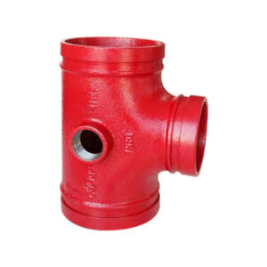
Grooved-increasing-tee-1-300x300.jpg))
Nous restons fidèles à notre mission, en stimulant l'innovation pour offrir des produits et des services exceptionnels à nos clients, offrir à nos employés des opportunités de croissance trans-formatives et créer une valeur durable pour la société.


