


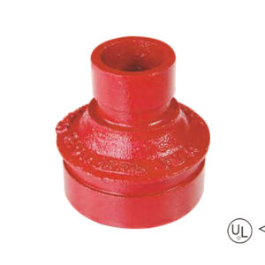
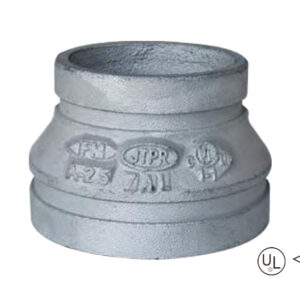
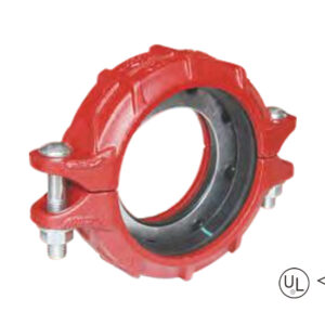
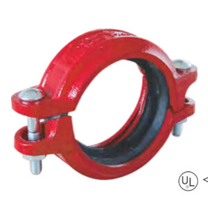
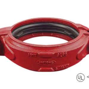
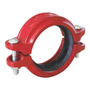
-Estándar: ANSI / UL 213C UL / FM
-Material: Fundición dúctil ASTM A536, 65-45-12
-Presión nominal: 300 - 500 psi
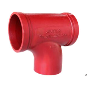
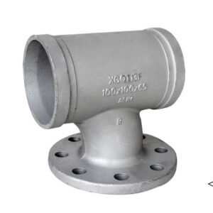
-Superficie: Pintura roja / galvanizado en caliente
-Gama de tallas: 1-1/4″×1″ – 12″×10″
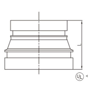
descripción
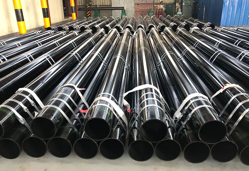
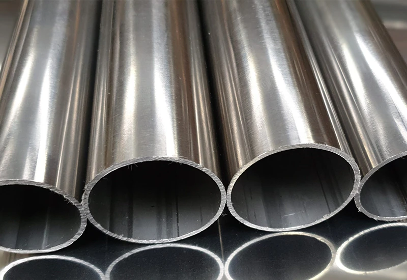
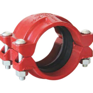
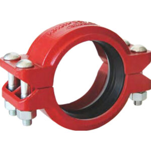
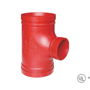
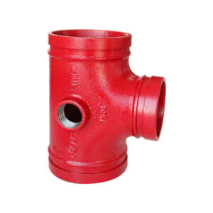
Grooved concentric reducer is a concentric reducer fitting. The diameters at both ends are different and the centerlines coincide. It is used to join pipes of different diameters by groove connection
Especificación
Tamaño disponible
Talla | Center to end | ||
En pulgadas | DN | mm | L(mm) |
1-1/4″ × 1″ | 32 × 25 | 42.4 × 33.7 | 64 |
1-1/2″ × 1″ | 40 × 25 | 48.3 × 33.7 | 64 |
1-1/2″ × 1-1/4″ | 40 × 32 | 48.3 × 42.4 | 64 |
2″ × 1″ | 50 × 25 | 60.3 × 33.7 | 64 |
2″ × 1-1/4″ | 50 × 32 | 60.3 × 42.4 | 64 |
2″ × 1-1/2″ | 50 × 40 | 60.3 × 48.3 | 64 |
2-1/2″ × 1″ | 65 × 25 | 73.0 × 33.7 | 64 |
2-1/2″ × 1-1/4″ | 65 × 32 | 73.0 × 42.4 | 64 |
2-1/2″ × 1-1/2″ | 65 × 40 | 73.0 × 48.3 | 64 |
2-1/2″ × 2″ | 65 × 50 | 73.0 × 60.3 | 64 |
2-1/2″ × 1″ | 65 × 25 | 76.1 × 33.7 | 64 |
2-1/2″ × 1-1/4″ | 65 × 32 | 76.1 × 42.4 | 64 |
2-1/2″ × 1-1/2″ | 65 × 40 | 76.1 × 48.3 | 64 |
2-1/2″ × 2″ | 65 × 50 | 76.1 × 60.3 | 64 |
3″ × 1″ | 80 × 25 | 88.9 × 33.7 | 64 |
3″ × 1-1/4″ | 80 × 32 | 88.9 × 42.4 | 64 |
3″ × 1-1/2″ | 80 × 40 | 88.9 × 48.3 | 64 |
3″ × 2″ | 80 × 50 | 88.9 × 60.3 | 64 |
3″ × 2-1/2″ | 80 × 65 | 88.9 × 73.0 | 64 |
3″ × 2-1/2″ | 80 × 65 | 88.9 × 76.1 | 64 |
4″ × 1-1/4″ | 100 × 32 | 114.3 × 42.4 | 76 |
4″ × 1-1/2″ | 100 × 40 | 114.3 × 48.3 | 76 |
4″ × 2″ | 100 × 50 | 114.3 × 60.3 | 76 |
4″ × 2-1/2″ | 100 × 65 | 114.3 × 73.0 | 76 |
4″ × 2-1/2″ | 100 × 65 | 114.3 × 76.1 | 76 |
4″ × 3″ | 100 × 80 | 114.3 × 88.9 | 76 |
5″ × 2″ | 125 × 50 | 139.7 × 60.3 | 89 |
5″ × 2-1/2″ | 125 × 65 | 139.7 × 76.1 | 89 |
5″ × 3″ | 125 × 80 | 139.7 × 88.9 | 89 |
5″ × 4″ | 125 × 100 | 139.7 × 114.3 | 89 |
5″ × 2-1/2″ | 125 × 65 | 141.3 × 73.0 | 89 |
5″ × 3″ | 125 × 80 | 141.3 × 88.9 | 89 |
5″ × 4″ | 125 × 100 | 141.3 × 114.3 | 89 |
6″ × 2″ | 150 × 50 | 165.1 × 60.3 | 102 |
6″ × 2-1/2″ | 150 × 65 | 165.1 × 76.1 | 102 |
6″ × 3″ | 150 × 80 | 165.1 × 88.9 | 102 |
6″ × 4″ | 150 × 100 | 165.1 × 114.3 | 102 |
6″ × 5″ | 150 × 125 | 165.1 × 139.7 | 102 |
6″ × 2″ | 150 × 50 | 168.3 × 60.3 | 102 |
6″ × 2-1/2″ | 150 × 65 | 168.3 × 73.0 | 102 |
6″ × 2-1/2″ | 150 × 65 | 168.3 × 76.1 | 102 |
6″ × 3″ | 150 × 80 | 168.3 × 88.9 | 102 |
6″ × 4″ | 150 × 100 | 168.3 × 114.3 | 102 |
6″ × 5″ | 150 × 125 | 168.3 × 139.7 | 102 |
6″ × 5″ | 150 × 125 | 168.3 × 141.3 | 102 |
8″ × 2″ | 200 × 50 | 219.1 × 60.3 | 127 |
8″ × 2-1/2″ | 200 × 65 | 219.1 × 73.0 | 127 |
8″ × 2-1/2″ | 200 × 65 | 219.1 × 76.1 | 127 |
8″ × 3″ | 200 × 80 | 219.1 × 88.9 | 127 |
8″ × 4″ | 200 × 100 | 219.1 × 114.3 | 127 |
8″ × 5″ | 200 × 125 | 219.1 × 139.7 | 127 |
8″ × 5″ | 200 × 125 | 219.1 × 141.3 | 127 |
8″ × 6″ | 200 × 150 | 219.1 × 165.1 | 127 |
8″ × 6″ | 200 × 150 | 219.1 × 168.3 | 127 |
10″ × 4″ | 250 × 100 | 273.0 × 114.3 | 152 |
10″ × 6″ | 250 × 150 | 273.0 × 165.1 | 152 |
10″ × 6″ | 250 × 150 | 273.0 × 168.3 | 152 |
10″ × 8″ | 250 × 200 | 273.0 × 219.1 | 152 |
12″ × 6″ | 300 × 150 | 323.9 × 165.1 | 178 |
12″ × 6″ | 300 × 150 | 323.9 × 168.3 | 178 |
12″ × 8″ | 300 × 200 | 323.9 × 219.1 | 178 |
12″ × 10″ | 300 × 250 | 323.9 × 273.0 | 178 |
aplicación
ventajas
1. Conical channel design zero resistance: The conical flow channels with concentric right angles reduce the fluid from the large pipe to the small pipe, so that all parts of the conduction become more smooth and smooth, which can reduce 40% loss;
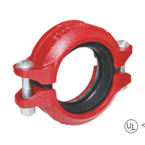
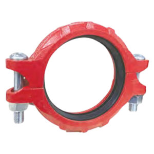
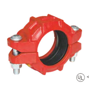
2. Grooved clamp connections, equipping with UL/FM certification, are able to bear 300-500psi pressure and resist water hammer effects, which is suited for seismic resistant and maintenance-free;
3. Installing Minutes: Double-grooved end design eliminates the need for alignment calibration and installation speeds are up to three times faster than flanged connections;
4. Extraordinary Environmental Adaptation: Cast Iron Body (ASTM A536) with red paint/hot dig galv coating, immune to chemical rust in addition to temperatures changes -30 °C to 150 °C.
embalaje
Tamaño disponible
Talla | Center to end | ||
En pulgadas | DN | mm | L(mm) |
1-1/4″ × 1″ | 32 × 25 | 42.4 × 33.7 | 64 |
1-1/2″ × 1″ | 40 × 25 | 48.3 × 33.7 | 64 |
1-1/2″ × 1-1/4″ | 40 × 32 | 48.3 × 42.4 | 64 |
2″ × 1″ | 50 × 25 | 60.3 × 33.7 | 64 |
2″ × 1-1/4″ | 50 × 32 | 60.3 × 42.4 | 64 |
2″ × 1-1/2″ | 50 × 40 | 60.3 × 48.3 | 64 |
2-1/2″ × 1″ | 65 × 25 | 73.0 × 33.7 | 64 |
2-1/2″ × 1-1/4″ | 65 × 32 | 73.0 × 42.4 | 64 |
2-1/2″ × 1-1/2″ | 65 × 40 | 73.0 × 48.3 | 64 |
2-1/2″ × 2″ | 65 × 50 | 73.0 × 60.3 | 64 |
2-1/2″ × 1″ | 65 × 25 | 76.1 × 33.7 | 64 |
2-1/2″ × 1-1/4″ | 65 × 32 | 76.1 × 42.4 | 64 |
2-1/2″ × 1-1/2″ | 65 × 40 | 76.1 × 48.3 | 64 |
2-1/2″ × 2″ | 65 × 50 | 76.1 × 60.3 | 64 |
3″ × 1″ | 80 × 25 | 88.9 × 33.7 | 64 |
3″ × 1-1/4″ | 80 × 32 | 88.9 × 42.4 | 64 |
3″ × 1-1/2″ | 80 × 40 | 88.9 × 48.3 | 64 |
3″ × 2″ | 80 × 50 | 88.9 × 60.3 | 64 |
3″ × 2-1/2″ | 80 × 65 | 88.9 × 73.0 | 64 |
3″ × 2-1/2″ | 80 × 65 | 88.9 × 76.1 | 64 |
4″ × 1-1/4″ | 100 × 32 | 114.3 × 42.4 | 76 |
4″ × 1-1/2″ | 100 × 40 | 114.3 × 48.3 | 76 |
4″ × 2″ | 100 × 50 | 114.3 × 60.3 | 76 |
4″ × 2-1/2″ | 100 × 65 | 114.3 × 73.0 | 76 |
4″ × 2-1/2″ | 100 × 65 | 114.3 × 76.1 | 76 |
4″ × 3″ | 100 × 80 | 114.3 × 88.9 | 76 |
5″ × 2″ | 125 × 50 | 139.7 × 60.3 | 89 |
5″ × 2-1/2″ | 125 × 65 | 139.7 × 76.1 | 89 |
5″ × 3″ | 125 × 80 | 139.7 × 88.9 | 89 |
5″ × 4″ | 125 × 100 | 139.7 × 114.3 | 89 |
5″ × 2-1/2″ | 125 × 65 | 141.3 × 73.0 | 89 |
5″ × 3″ | 125 × 80 | 141.3 × 88.9 | 89 |
5″ × 4″ | 125 × 100 | 141.3 × 114.3 | 89 |
6″ × 2″ | 150 × 50 | 165.1 × 60.3 | 102 |
6″ × 2-1/2″ | 150 × 65 | 165.1 × 76.1 | 102 |
6″ × 3″ | 150 × 80 | 165.1 × 88.9 | 102 |
6″ × 4″ | 150 × 100 | 165.1 × 114.3 | 102 |
6″ × 5″ | 150 × 125 | 165.1 × 139.7 | 102 |
6″ × 2″ | 150 × 50 | 168.3 × 60.3 | 102 |
6″ × 2-1/2″ | 150 × 65 | 168.3 × 73.0 | 102 |
6″ × 2-1/2″ | 150 × 65 | 168.3 × 76.1 | 102 |
6″ × 3″ | 150 × 80 | 168.3 × 88.9 | 102 |
6″ × 4″ | 150 × 100 | 168.3 × 114.3 | 102 |
6″ × 5″ | 150 × 125 | 168.3 × 139.7 | 102 |
6″ × 5″ | 150 × 125 | 168.3 × 141.3 | 102 |
8″ × 2″ | 200 × 50 | 219.1 × 60.3 | 127 |
8″ × 2-1/2″ | 200 × 65 | 219.1 × 73.0 | 127 |
8″ × 2-1/2″ | 200 × 65 | 219.1 × 76.1 | 127 |
8″ × 3″ | 200 × 80 | 219.1 × 88.9 | 127 |
8″ × 4″ | 200 × 100 | 219.1 × 114.3 | 127 |
8″ × 5″ | 200 × 125 | 219.1 × 139.7 | 127 |
8″ × 5″ | 200 × 125 | 219.1 × 141.3 | 127 |
8″ × 6″ | 200 × 150 | 219.1 × 165.1 | 127 |
8″ × 6″ | 200 × 150 | 219.1 × 168.3 | 127 |
10″ × 4″ | 250 × 100 | 273.0 × 114.3 | 152 |
10″ × 6″ | 250 × 150 | 273.0 × 165.1 | 152 |
10″ × 6″ | 250 × 150 | 273.0 × 168.3 | 152 |
10″ × 8″ | 250 × 200 | 273.0 × 219.1 | 152 |
12″ × 6″ | 300 × 150 | 323.9 × 165.1 | 178 |
12″ × 6″ | 300 × 150 | 323.9 × 168.3 | 178 |
12″ × 8″ | 300 × 200 | 323.9 × 219.1 | 178 |
12″ × 10″ | 300 × 250 | 323.9 × 273.0 | 178 |
1. Conical channel design zero resistance: The conical flow channels with concentric right angles reduce the fluid from the large pipe to the small pipe, so that all parts of the conduction become more smooth and smooth, which can reduce 40% loss;
2. Grooved clamp connections, equipping with UL/FM certification, are able to bear 300-500psi pressure and resist water hammer effects, which is suited for seismic resistant and maintenance-free;
3. Installing Minutes: Double-grooved end design eliminates the need for alignment calibration and installation speeds are up to three times faster than flanged connections;
4. Extraordinary Environmental Adaptation: Cast Iron Body (ASTM A536) with red paint/hot dig galv coating, immune to chemical rust in addition to temperatures changes -30 °C to 150 °C.
Facilítenos los detalles de su proyecto (como aplicación, especificaciones, cantidad). Nuestro experimentado equipo le responderá con una solución a medida y un presupuesto competitivo en un plazo de 24 horas laborables.
T-raci-incremental-ranurada-1-300x300.jpg)
Nos mantenemos firmes en nuestra misión, impulsando la innovación para ofrecer productos y servicios excepcionales a los clientes, capacitar a los empleados con oportunidades de crecimiento trans-formativo y crear valor sostenible para la sociedad.
