


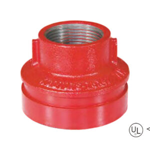
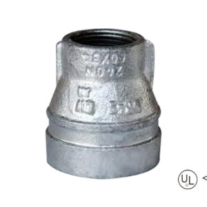
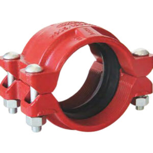
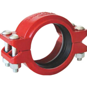
·Standard: ANSI / UL 213C UL / FM
·Material: Ductile iron ASTM A536, 65-45-12
·Thread run: Female thread, NPT / BSPT
·Rated pressure: 300 – 500 psi
·Surface: Red painting / hot dip galvanized
·Size range: 1-1/2”×1” – 8″×4″
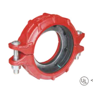
description
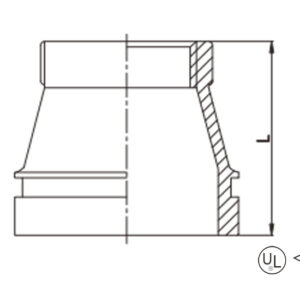
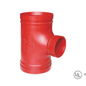
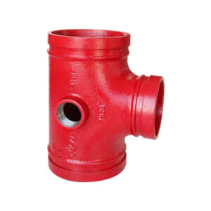
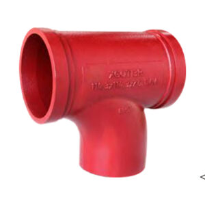
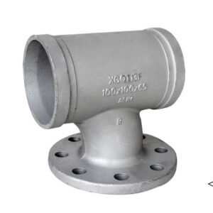
Grooved concentric reducer with female threaded outlet is a concentric reducer with different pipe diameters at both ends and overlapping centerlines. The outlet end is designed with an internal thread and is used to connect pipes of different pipe diameters and adapt to internal thread components
Specification
Available size
Size | End to end | ||
Inch | DN | mm | L(mm) |
1-1/2” × 1” | 40 × 25 | 48.3 × 33.7 | 64 |
2″ × 1/2″ | 50 × 15 | 60.3 × 21.3 | 64 |
2″ × 3/4″ | 50 × 20 | 60.3 × 26.9 | 64 |
2″ × 1″ | 50 × 25 | 60.3 × 33.7 | 64 |
2″ × 1-1/4″ | 50 × 32 | 60.3 × 42.4 | 64 |
2″ × 1-1/2″ | 50 × 40 | 60.3 × 48.3 | 64 |
2-1/2″ × 1″ | 65 × 25 | 73.0 × 33.7 | 64 |
2-1/2″ × 1-1/4″ | 65 × 32 | 73.0 × 42.4 | 64 |
2-1/2″ × 1-1/2″ | 65 × 40 | 73.0 × 48.3 | 64 |
2-1/2″ × 2″ | 65 × 50 | 73.0 × 60.3 | 64 |
2-1/2″ × 1/2″ | 65 × 15 | 76.1 × 21.3 | 64 |
2-1/2″ × 3/4″ | 65 × 20 | 76.1 × 26.9 | 64 |
2-1/2″ × 1″ | 65 × 25 | 76.1 × 33.7 | 64 |
2-1/2″ × 1-1/4″ | 65 × 32 | 76.1 × 42.4 | 64 |
2-1/2″ × 1-1/2″ | 65 × 40 | 76.1 × 48.3 | 64 |
2-1/2″ × 2″ | 65 × 50 | 76.1 × 60.3 | 64 |
3″ × 1″ | 80 × 25 | 88.9 × 33.7 | 64 |
3″ × 1-1/4″ | 80 × 32 | 88.9 × 42.4 | 64 |
3″ × 1-1/2″ | 80 × 40 | 88.9 × 48.3 | 64 |
3″ × 2″ | 80 × 50 | 88.9 × 60.3 | 64 |
3″ × 2-1/2″ | 80 × 65 | 88.9 × 73.0 | 64 |
3″ × 2-1/2″ | 80 × 65 | 88.9 × 76.1 | 64 |
4″ × 1″ | 100 × 25 | 114.3 × 33.7 | 76 |
4″ × 1-1/4″ | 100 × 32 | 114.3 × 42.4 | 76 |
4″ × 1-1/2″ | 100 × 40 | 114.3 × 48.3 | 76 |
4″ × 2″ | 100 × 50 | 114.3 × 60.3 | 76 |
4″ × 2-1/2″ | 100 × 65 | 114.3 × 73.0 | 76 |
4″ × 2-1/2″ | 100 × 65 | 114.3 × 76.1 | 76 |
4″ × 3″ | 100 × 80 | 114.3 × 88.9 | 76 |
5″ × 1″ | 125 × 25 | 139.7 × 33.7 | 89 |
5″ × 1-1/4″ | 125 × 32 | 139.7 × 42.4 | 89 |
5″ × 1-1/2″ | 125 × 40 | 139.7 × 48.3 | 89 |
5″ × 2″ | 125 × 50 | 139.7 × 60.3 | 89 |
5″ × 2-1/2″ | 125 × 65 | 139.7 × 76.1 | 89 |
5″ × 3″ | 125 × 80 | 139.7 × 88.9 | 89 |
5″ × 4″ | 125 × 100 | 139.7 × 114.3 | 89 |
6″ × 1″ | 150 × 25 | 165.1 × 33.7 | 102 |
6″ × 1-1/4″ | 150 × 32 | 165.1 × 42.4 | 102 |
6″ × 1-1/2″ | 150 × 40 | 165.1 × 48.3 | 102 |
6″ × 2″ | 150 × 50 | 165.1 × 60.3 | 102 |
6″ × 2-1/2″ | 150 × 65 | 165.1 × 76.1 | 102 |
6″ × 3″ | 150 × 80 | 165.1 × 88.9 | 102 |
6″ × 4″ | 150 × 100 | 165.1 × 114.3 | 102 |
6″ × 1″ | 150 × 25 | 168.3 × 33.7 | 102 |
6″ × 2″ | 150 × 50 | 168.3 × 60.3 | 102 |
6″ × 3″ | 150 × 80 | 168.3 × 88.9 | 102 |
6″ × 4″ | 150 × 100 | 168.3 × 114.3 | 102 |
8″ × 1-1/2″ | 200 × 40 | 219.1 × 48.3 | 127 |
6″ × 4″ | 150 × 100 | 168.3 × 114.3 | 102 |
8″ × 1-1/2″ | 200 × 40 | 219.1 × 48.3 | 127 |
8″ × 2″ | 200 × 50 | 219.1 × 60.3 | 127 |
8″ × 2-1/2″ | 200 × 65 | 219.1 × 76.1 | 127 |
8″ × 3″ | 200 × 80 | 219.1 × 88.9 | 127 |
8″ × 4″ | 200 × 100 | 219.1 × 114.3 | 127 |
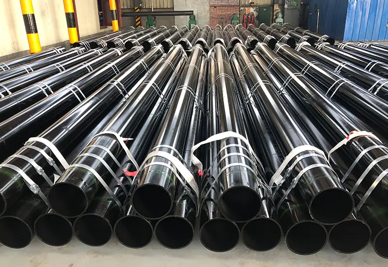
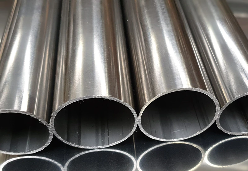
application
advantages
1. Three integrative design:Concentric Reducer: Coaxial alignment, smooth fluid flow during transition, and 30% lower pressure loss;Groove Connection: GROOVE system with quick-fit fittings on main lines at both ends, high seismic resistance and 300-500 psi rated pressure class; Internal Threaded Branch Pipes (NPT/BSPT): All calibration equipment by tightening the internal thread to eliminate sealing point.
2. Installation Along Minute: Energy Groove Connection, Save Welding or Flange Alignment;Thread Branch pipeline Direct Screw to the equipment(e.g. fuel tank);Triple Speed for Installation of Thread branch pipelines
3. Extraordinary environmental resistance: Ductile iron body(ASTM A536) with red paint/hot-dip galvanized, liquid epoxy coated which is anti-resistant to chemical corrosion and provide excellent mechanical stabilities in the temperature range of -30°C to 150°
4. All-scenario compatibility: Compatible with pipe sizes ranging from 1-1¼”×1” to 8”×4” (DN40-DN200), so able to meet wide range of needs from residential to industrial applications
packing
Available size
Size | End to end | ||
Inch | DN | mm | L(mm) |
1-1/2” × 1” | 40 × 25 | 48.3 × 33.7 | 64 |
2″ × 1/2″ | 50 × 15 | 60.3 × 21.3 | 64 |
2″ × 3/4″ | 50 × 20 | 60.3 × 26.9 | 64 |
2″ × 1″ | 50 × 25 | 60.3 × 33.7 | 64 |
2″ × 1-1/4″ | 50 × 32 | 60.3 × 42.4 | 64 |
2″ × 1-1/2″ | 50 × 40 | 60.3 × 48.3 | 64 |
2-1/2″ × 1″ | 65 × 25 | 73.0 × 33.7 | 64 |
2-1/2″ × 1-1/4″ | 65 × 32 | 73.0 × 42.4 | 64 |
2-1/2″ × 1-1/2″ | 65 × 40 | 73.0 × 48.3 | 64 |
2-1/2″ × 2″ | 65 × 50 | 73.0 × 60.3 | 64 |
2-1/2″ × 1/2″ | 65 × 15 | 76.1 × 21.3 | 64 |
2-1/2″ × 3/4″ | 65 × 20 | 76.1 × 26.9 | 64 |
2-1/2″ × 1″ | 65 × 25 | 76.1 × 33.7 | 64 |
2-1/2″ × 1-1/4″ | 65 × 32 | 76.1 × 42.4 | 64 |
2-1/2″ × 1-1/2″ | 65 × 40 | 76.1 × 48.3 | 64 |
2-1/2″ × 2″ | 65 × 50 | 76.1 × 60.3 | 64 |
3″ × 1″ | 80 × 25 | 88.9 × 33.7 | 64 |
3″ × 1-1/4″ | 80 × 32 | 88.9 × 42.4 | 64 |
3″ × 1-1/2″ | 80 × 40 | 88.9 × 48.3 | 64 |
3″ × 2″ | 80 × 50 | 88.9 × 60.3 | 64 |
3″ × 2-1/2″ | 80 × 65 | 88.9 × 73.0 | 64 |
3″ × 2-1/2″ | 80 × 65 | 88.9 × 76.1 | 64 |
4″ × 1″ | 100 × 25 | 114.3 × 33.7 | 76 |
4″ × 1-1/4″ | 100 × 32 | 114.3 × 42.4 | 76 |
4″ × 1-1/2″ | 100 × 40 | 114.3 × 48.3 | 76 |
4″ × 2″ | 100 × 50 | 114.3 × 60.3 | 76 |
4″ × 2-1/2″ | 100 × 65 | 114.3 × 73.0 | 76 |
4″ × 2-1/2″ | 100 × 65 | 114.3 × 76.1 | 76 |
4″ × 3″ | 100 × 80 | 114.3 × 88.9 | 76 |
5″ × 1″ | 125 × 25 | 139.7 × 33.7 | 89 |
5″ × 1-1/4″ | 125 × 32 | 139.7 × 42.4 | 89 |
5″ × 1-1/2″ | 125 × 40 | 139.7 × 48.3 | 89 |
5″ × 2″ | 125 × 50 | 139.7 × 60.3 | 89 |
5″ × 2-1/2″ | 125 × 65 | 139.7 × 76.1 | 89 |
5″ × 3″ | 125 × 80 | 139.7 × 88.9 | 89 |
5″ × 4″ | 125 × 100 | 139.7 × 114.3 | 89 |
6″ × 1″ | 150 × 25 | 165.1 × 33.7 | 102 |
6″ × 1-1/4″ | 150 × 32 | 165.1 × 42.4 | 102 |
6″ × 1-1/2″ | 150 × 40 | 165.1 × 48.3 | 102 |
6″ × 2″ | 150 × 50 | 165.1 × 60.3 | 102 |
6″ × 2-1/2″ | 150 × 65 | 165.1 × 76.1 | 102 |
6″ × 3″ | 150 × 80 | 165.1 × 88.9 | 102 |
6″ × 4″ | 150 × 100 | 165.1 × 114.3 | 102 |
6″ × 1″ | 150 × 25 | 168.3 × 33.7 | 102 |
6″ × 2″ | 150 × 50 | 168.3 × 60.3 | 102 |
6″ × 3″ | 150 × 80 | 168.3 × 88.9 | 102 |
6″ × 4″ | 150 × 100 | 168.3 × 114.3 | 102 |
8″ × 1-1/2″ | 200 × 40 | 219.1 × 48.3 | 127 |
6″ × 4″ | 150 × 100 | 168.3 × 114.3 | 102 |
8″ × 1-1/2″ | 200 × 40 | 219.1 × 48.3 | 127 |
8″ × 2″ | 200 × 50 | 219.1 × 60.3 | 127 |
8″ × 2-1/2″ | 200 × 65 | 219.1 × 76.1 | 127 |
8″ × 3″ | 200 × 80 | 219.1 × 88.9 | 127 |
8″ × 4″ | 200 × 100 | 219.1 × 114.3 | 127 |
1. Three integrative design:Concentric Reducer: Coaxial alignment, smooth fluid flow during transition, and 30% lower pressure loss;Groove Connection: GROOVE system with quick-fit fittings on main lines at both ends, high seismic resistance and 300-500 psi rated pressure class; Internal Threaded Branch Pipes (NPT/BSPT): All calibration equipment by tightening the internal thread to eliminate sealing point.
2. Installation Along Minute: Energy Groove Connection, Save Welding or Flange Alignment;Thread Branch pipeline Direct Screw to the equipment(e.g. fuel tank);Triple Speed for Installation of Thread branch pipelines
3. Extraordinary environmental resistance: Ductile iron body(ASTM A536) with red paint/hot-dip galvanized, liquid epoxy coated which is anti-resistant to chemical corrosion and provide excellent mechanical stabilities in the temperature range of -30°C to 150°
4. All-scenario compatibility: Compatible with pipe sizes ranging from 1-1¼”×1” to 8”×4” (DN40-DN200), so able to meet wide range of needs from residential to industrial applications
Provide us with your project details (like application, specifications, quantity). Our experienced team will respond with a tailored solution and competitive quote within 24 business hours.
Grooved-increasing-tee-1-300x300.jpg)
We remain steadfast in our mission, driving innovation to deliver exceptional products and services for clients, empower employees with trans-formative growth opportunities, and create sustainable value for society.

