


-Estándar: ANSI / UL 213C UL / FM
-Material: Fundición dúctil ASTM A536, 65-45-12
-Hilo corrido: Rosca hembra, NPT / BSPT
-Presión nominal: 300 - 500 psi
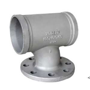
-Superficie: Pintura roja / galvanizado en caliente
-Gama de tallas: 1-1/2”×1” – 8″×4″
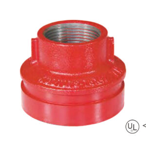
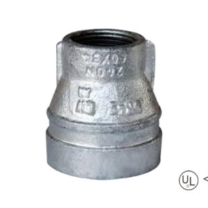
descripción
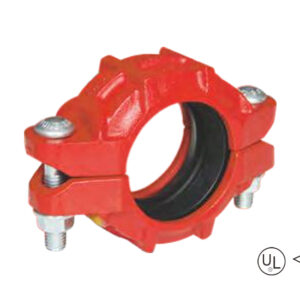
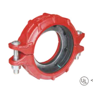
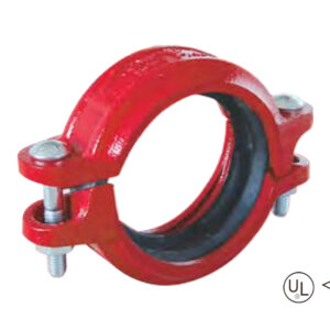
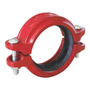
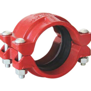
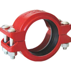
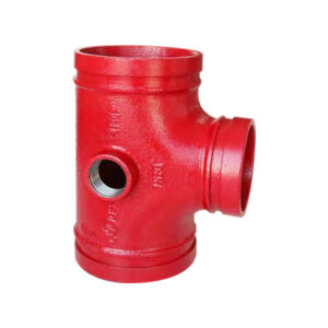
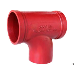
Grooved concentric reducer with female threaded outlet is a concentric reducer with different pipe diameters at both ends and overlapping centerlines. The outlet end is designed with an internal thread and is used to connect pipes of different pipe diameters and adapt to internal thread components
Especificación
Tamaño disponible
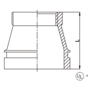
Talla | De extremo a extremo | ||
En pulgadas | DN | mm | L(mm) |
1-1/2” × 1” | 40 × 25 | 48.3 × 33.7 | 64 |
2″ × 1/2″ | 50 × 15 | 60.3 × 21.3 | 64 |
2″ × 3/4″ | 50 × 20 | 60.3 × 26.9 | 64 |
2″ × 1″ | 50 × 25 | 60.3 × 33.7 | 64 |
2″ × 1-1/4″ | 50 × 32 | 60.3 × 42.4 | 64 |
2″ × 1-1/2″ | 50 × 40 | 60.3 × 48.3 | 64 |
2-1/2″ × 1″ | 65 × 25 | 73.0 × 33.7 | 64 |
2-1/2″ × 1-1/4″ | 65 × 32 | 73.0 × 42.4 | 64 |
2-1/2″ × 1-1/2″ | 65 × 40 | 73.0 × 48.3 | 64 |
2-1/2″ × 2″ | 65 × 50 | 73.0 × 60.3 | 64 |
2-1/2″ × 1/2″ | 65 × 15 | 76.1 × 21.3 | 64 |
2-1/2″ × 3/4″ | 65 × 20 | 76.1 × 26.9 | 64 |
2-1/2″ × 1″ | 65 × 25 | 76.1 × 33.7 | 64 |
2-1/2″ × 1-1/4″ | 65 × 32 | 76.1 × 42.4 | 64 |
2-1/2″ × 1-1/2″ | 65 × 40 | 76.1 × 48.3 | 64 |
2-1/2″ × 2″ | 65 × 50 | 76.1 × 60.3 | 64 |
3″ × 1″ | 80 × 25 | 88.9 × 33.7 | 64 |
3″ × 1-1/4″ | 80 × 32 | 88.9 × 42.4 | 64 |
3″ × 1-1/2″ | 80 × 40 | 88.9 × 48.3 | 64 |
3″ × 2″ | 80 × 50 | 88.9 × 60.3 | 64 |
3″ × 2-1/2″ | 80 × 65 | 88.9 × 73.0 | 64 |
3″ × 2-1/2″ | 80 × 65 | 88.9 × 76.1 | 64 |
4″ × 1″ | 100 × 25 | 114.3 × 33.7 | 76 |
4″ × 1-1/4″ | 100 × 32 | 114.3 × 42.4 | 76 |
4″ × 1-1/2″ | 100 × 40 | 114.3 × 48.3 | 76 |
4″ × 2″ | 100 × 50 | 114.3 × 60.3 | 76 |
4″ × 2-1/2″ | 100 × 65 | 114.3 × 73.0 | 76 |
4″ × 2-1/2″ | 100 × 65 | 114.3 × 76.1 | 76 |
4″ × 3″ | 100 × 80 | 114.3 × 88.9 | 76 |
5″ × 1″ | 125 × 25 | 139.7 × 33.7 | 89 |
5″ × 1-1/4″ | 125 × 32 | 139.7 × 42.4 | 89 |
5″ × 1-1/2″ | 125 × 40 | 139.7 × 48.3 | 89 |
5″ × 2″ | 125 × 50 | 139.7 × 60.3 | 89 |
5″ × 2-1/2″ | 125 × 65 | 139.7 × 76.1 | 89 |
5″ × 3″ | 125 × 80 | 139.7 × 88.9 | 89 |
5″ × 4″ | 125 × 100 | 139.7 × 114.3 | 89 |
6″ × 1″ | 150 × 25 | 165.1 × 33.7 | 102 |
6″ × 1-1/4″ | 150 × 32 | 165.1 × 42.4 | 102 |
6″ × 1-1/2″ | 150 × 40 | 165.1 × 48.3 | 102 |
6″ × 2″ | 150 × 50 | 165.1 × 60.3 | 102 |
6″ × 2-1/2″ | 150 × 65 | 165.1 × 76.1 | 102 |
6″ × 3″ | 150 × 80 | 165.1 × 88.9 | 102 |
6″ × 4″ | 150 × 100 | 165.1 × 114.3 | 102 |
6″ × 1″ | 150 × 25 | 168.3 × 33.7 | 102 |
6″ × 2″ | 150 × 50 | 168.3 × 60.3 | 102 |
6″ × 3″ | 150 × 80 | 168.3 × 88.9 | 102 |
6″ × 4″ | 150 × 100 | 168.3 × 114.3 | 102 |
8″ × 1-1/2″ | 200 × 40 | 219.1 × 48.3 | 127 |
6″ × 4″ | 150 × 100 | 168.3 × 114.3 | 102 |
8″ × 1-1/2″ | 200 × 40 | 219.1 × 48.3 | 127 |
8″ × 2″ | 200 × 50 | 219.1 × 60.3 | 127 |
8″ × 2-1/2″ | 200 × 65 | 219.1 × 76.1 | 127 |
8″ × 3″ | 200 × 80 | 219.1 × 88.9 | 127 |
8″ × 4″ | 200 × 100 | 219.1 × 114.3 | 127 |
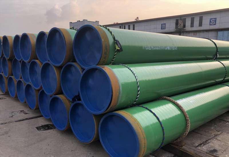
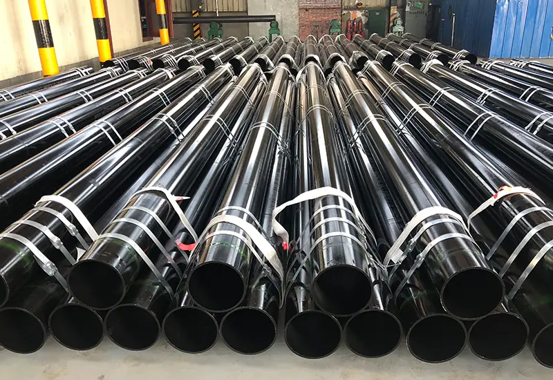
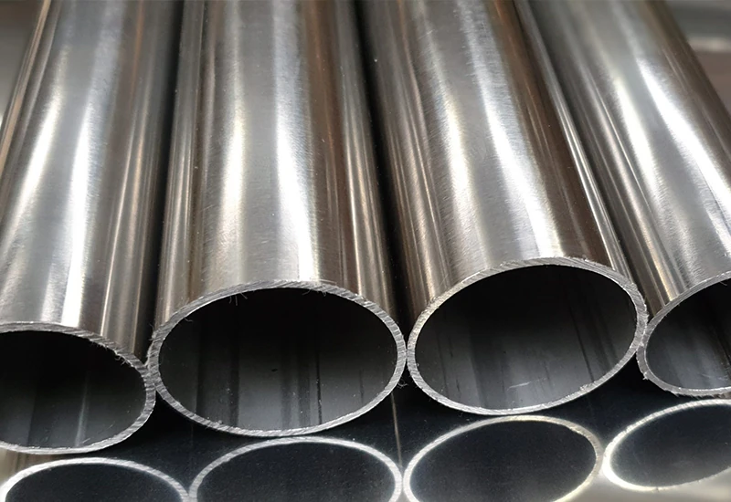
aplicación
ventajas
1. Three integrative design:Concentric Reducer: Coaxial alignment, smooth fluid flow during transition, and 30% lower pressure loss;Groove Connection: GROOVE system with quick-fit fittings on main lines at both ends, high seismic resistance and 300-500 psi rated pressure class; Internal Threaded Branch Pipes (NPT/BSPT): All calibration equipment by tightening the internal thread to eliminate sealing point.
2. Installation Along Minute: Energy Groove Connection, Save Welding or Flange Alignment;Thread Branch pipeline Direct Screw to the equipment(e.g. fuel tank);Triple Speed for Installation of Thread branch pipelines
3. Extraordinary environmental resistance: Ductile iron body(ASTM A536) with red paint/hot-dip galvanized, liquid epoxy coated which is anti-resistant to chemical corrosion and provide excellent mechanical stabilities in the temperature range of -30°C to 150°
4. All-scenario compatibility: Compatible with pipe sizes ranging from 1-1¼”×1” to 8”×4” (DN40-DN200), so able to meet wide range of needs from residential to industrial applications
embalaje
Tamaño disponible
Talla | De extremo a extremo | ||
En pulgadas | DN | mm | L(mm) |
1-1/2” × 1” | 40 × 25 | 48.3 × 33.7 | 64 |
2″ × 1/2″ | 50 × 15 | 60.3 × 21.3 | 64 |
2″ × 3/4″ | 50 × 20 | 60.3 × 26.9 | 64 |
2″ × 1″ | 50 × 25 | 60.3 × 33.7 | 64 |
2″ × 1-1/4″ | 50 × 32 | 60.3 × 42.4 | 64 |
2″ × 1-1/2″ | 50 × 40 | 60.3 × 48.3 | 64 |
2-1/2″ × 1″ | 65 × 25 | 73.0 × 33.7 | 64 |
2-1/2″ × 1-1/4″ | 65 × 32 | 73.0 × 42.4 | 64 |
2-1/2″ × 1-1/2″ | 65 × 40 | 73.0 × 48.3 | 64 |
2-1/2″ × 2″ | 65 × 50 | 73.0 × 60.3 | 64 |
2-1/2″ × 1/2″ | 65 × 15 | 76.1 × 21.3 | 64 |
2-1/2″ × 3/4″ | 65 × 20 | 76.1 × 26.9 | 64 |
2-1/2″ × 1″ | 65 × 25 | 76.1 × 33.7 | 64 |
2-1/2″ × 1-1/4″ | 65 × 32 | 76.1 × 42.4 | 64 |
2-1/2″ × 1-1/2″ | 65 × 40 | 76.1 × 48.3 | 64 |
2-1/2″ × 2″ | 65 × 50 | 76.1 × 60.3 | 64 |
3″ × 1″ | 80 × 25 | 88.9 × 33.7 | 64 |
3″ × 1-1/4″ | 80 × 32 | 88.9 × 42.4 | 64 |
3″ × 1-1/2″ | 80 × 40 | 88.9 × 48.3 | 64 |
3″ × 2″ | 80 × 50 | 88.9 × 60.3 | 64 |
3″ × 2-1/2″ | 80 × 65 | 88.9 × 73.0 | 64 |
3″ × 2-1/2″ | 80 × 65 | 88.9 × 76.1 | 64 |
4″ × 1″ | 100 × 25 | 114.3 × 33.7 | 76 |
4″ × 1-1/4″ | 100 × 32 | 114.3 × 42.4 | 76 |
4″ × 1-1/2″ | 100 × 40 | 114.3 × 48.3 | 76 |
4″ × 2″ | 100 × 50 | 114.3 × 60.3 | 76 |
4″ × 2-1/2″ | 100 × 65 | 114.3 × 73.0 | 76 |
4″ × 2-1/2″ | 100 × 65 | 114.3 × 76.1 | 76 |
4″ × 3″ | 100 × 80 | 114.3 × 88.9 | 76 |
5″ × 1″ | 125 × 25 | 139.7 × 33.7 | 89 |
5″ × 1-1/4″ | 125 × 32 | 139.7 × 42.4 | 89 |
5″ × 1-1/2″ | 125 × 40 | 139.7 × 48.3 | 89 |
5″ × 2″ | 125 × 50 | 139.7 × 60.3 | 89 |
5″ × 2-1/2″ | 125 × 65 | 139.7 × 76.1 | 89 |
5″ × 3″ | 125 × 80 | 139.7 × 88.9 | 89 |
5″ × 4″ | 125 × 100 | 139.7 × 114.3 | 89 |
6″ × 1″ | 150 × 25 | 165.1 × 33.7 | 102 |
6″ × 1-1/4″ | 150 × 32 | 165.1 × 42.4 | 102 |
6″ × 1-1/2″ | 150 × 40 | 165.1 × 48.3 | 102 |
6″ × 2″ | 150 × 50 | 165.1 × 60.3 | 102 |
6″ × 2-1/2″ | 150 × 65 | 165.1 × 76.1 | 102 |
6″ × 3″ | 150 × 80 | 165.1 × 88.9 | 102 |
6″ × 4″ | 150 × 100 | 165.1 × 114.3 | 102 |
6″ × 1″ | 150 × 25 | 168.3 × 33.7 | 102 |
6″ × 2″ | 150 × 50 | 168.3 × 60.3 | 102 |
6″ × 3″ | 150 × 80 | 168.3 × 88.9 | 102 |
6″ × 4″ | 150 × 100 | 168.3 × 114.3 | 102 |
8″ × 1-1/2″ | 200 × 40 | 219.1 × 48.3 | 127 |
6″ × 4″ | 150 × 100 | 168.3 × 114.3 | 102 |
8″ × 1-1/2″ | 200 × 40 | 219.1 × 48.3 | 127 |
8″ × 2″ | 200 × 50 | 219.1 × 60.3 | 127 |
8″ × 2-1/2″ | 200 × 65 | 219.1 × 76.1 | 127 |
8″ × 3″ | 200 × 80 | 219.1 × 88.9 | 127 |
8″ × 4″ | 200 × 100 | 219.1 × 114.3 | 127 |
1. Three integrative design:Concentric Reducer: Coaxial alignment, smooth fluid flow during transition, and 30% lower pressure loss;Groove Connection: GROOVE system with quick-fit fittings on main lines at both ends, high seismic resistance and 300-500 psi rated pressure class; Internal Threaded Branch Pipes (NPT/BSPT): All calibration equipment by tightening the internal thread to eliminate sealing point.
2. Installation Along Minute: Energy Groove Connection, Save Welding or Flange Alignment;Thread Branch pipeline Direct Screw to the equipment(e.g. fuel tank);Triple Speed for Installation of Thread branch pipelines
3. Extraordinary environmental resistance: Ductile iron body(ASTM A536) with red paint/hot-dip galvanized, liquid epoxy coated which is anti-resistant to chemical corrosion and provide excellent mechanical stabilities in the temperature range of -30°C to 150°
4. All-scenario compatibility: Compatible with pipe sizes ranging from 1-1¼”×1” to 8”×4” (DN40-DN200), so able to meet wide range of needs from residential to industrial applications
Facilítenos los detalles de su proyecto (como aplicación, especificaciones, cantidad). Nuestro experimentado equipo le responderá con una solución a medida y un presupuesto competitivo en un plazo de 24 horas laborables.
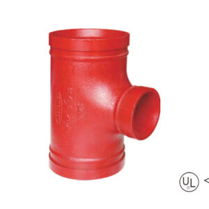
T-raci-incremental-ranurada-1-300x300.jpg)
Nos mantenemos firmes en nuestra misión, impulsando la innovación para ofrecer productos y servicios excepcionales a los clientes, capacitar a los empleados con oportunidades de crecimiento trans-formativo y crear valor sostenible para la sociedad.